![[Datsun 1200 encyclopedia]](/wiki/upload/wiki.png)
| Revision as of 02:29, 4 May 2009 ddgonzal (Talk | contribs) <- Previous diff |
Revision as of 02:32, 4 May 2009 ddgonzal (Talk | contribs) (->Upgrades) Next diff -> |
||
| Line 209: | Line 209: | ||
| # Physical swap. How does it bolt to the A12 engine? | # Physical swap. How does it bolt to the A12 engine? | ||
| # Electrical swap. How will the new alternator be connected to the wiring? | # Electrical swap. How will the new alternator be connected to the wiring? | ||
| + | |||
| + | Early A engine (1966-1973) has limited room for alternator. It is mounted low, under manifolds, on left side of engine. The larger 50A alternator will bolt to the bracket, but the alternator rubs against the lower radiator hose. It could be made to work, but is not recommended. | ||
| For more details, see [[Alternator Upgrades]]. | For more details, see [[Alternator Upgrades]]. | ||
Revision as of 02:32, 4 May 2009
Datsun 1200 was fitted with a lightweight (8.4 pound) 35 AMP Hitachi alternator. These alternators will usually last 10-15 years or more than 100,000 miles before maintainence is required. The only normal maintainence is to replace the brushes when the dashboard alternator light starts flickering. The alternator uses an external Voltage regulator.
Contents |
Mounting
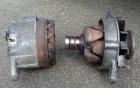
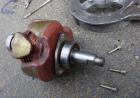
Early A-series engines (1966-1973) mount the alternator down low on the left side of the engine, under the intake manifold as shown in this photo:
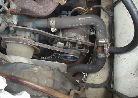
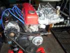
1974-up engines mount it high on the right side of the engine. For the A Engine Redesign, the alternator was moved to this position to make room for an Air conditioning pump or Smog pump.
Wiring
See: Wiring article.
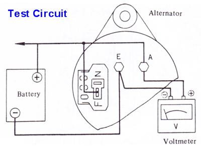
Testing
The alternator has four terminals:
- A - alternator connects to Battery cable + 12V via large white/red wire.
- E - earth/ground. Connected to case of alternator, hence though bracket to the engine. Engine is grounded by black cable (part of the two-cable negative battery cable)
- F - the Field. This needs 12V to get the alternator working. The Voltage regulator turns this on/off (12V) rapidly to achieve an average of 13.5-15.0 volts
- N - Nuetral point. This is connected to the dash Lamp. This is optional, the alternator will function with this disconnected.
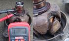
Test Procedures
- With engine running at 1100 rpm, measure Voltage across battery cable. If it reads between 13.5-15.0 volts, everything is fine (or over 12.5 volts headlights on main beams)
- Measure Ohms between F & E terminals. It should be approxmiately 5 ohms (with ohmmeter on lowest range). If higher or lower, remove alternator and inspect.
- Perform Regulator Bypass Test
- Be sure to test at A & E terminals, to bypass external wiring problems
- Disconnect T-shaped connector (F+N) at alternator, to bypass the regulator wiring
- Jump the F terminal to Battery +
- Test with headlight main beams on
-
- Output at 1100 should be 12.5 volts or higher
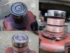
Brushes
Brush comparo:
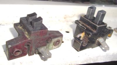
- Left: worn down to the limit line
- right: New
These just unbolt from the rear of the alternator, very easy to check and replace if necessary.
Rotor
After removing the brushes, you can test the rotor. Or disassemble the alternator.
Using an ohmmeter, check between the two copper slip rings:
- Should be around 4.4 ohms (with ohmmeter on lowest range)
- No continuity means the winding is broken or detached
- Lower ohms may indicate a short, perhaps from bad insulation
- Neither condition is easily fixable. Replace it.
Also check for isolation:
- There should be no continuity (even using 1M-ohm scale) between either ring and the rotor metal or shaft.
- If there is, it is shorted. Replace it.
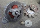
Disassembly
- Remove the brush holder assembly
- Remove the three 8mm-head long bolts from the rear face. You can use an 8mm socket or 5/16" socket.
- Then separate like this:
-
Note that one through-bolt is longer than the other two.
Rotor Maintainence
- Rear Bearing Repack: Carefully pry up a bit of the retainer and pack it with high-temp wheel bearing grease. Then carefully tamp the metal back down.
-
- Clean the slip rings with ether and polish with super-fine (400 or 600 grit) non-ferrite sand paper.
- Wipe off all grease. Carefully remove excess grease from back side of bearing and slip rings.
- The front bearing can be packed in a similar way.
To check if the bearings need changing or packing, spin them. They should be silent, and not spin free which indicate there is no more grease in them. They should turn easily, smoothly and silently.
To get to the front bearing:
- Remove the pulley with a 13/16" box wrench or socket
- Use a large screwdriver in the pulley fins to hold it steady while removing the nut
- After the pulley is off, remove the three screws hold the bearing retainer. Then separate the rotor from the aluminum case plate.
-
Rear Bearing
- NSK 620-1Z (metal retainer) or 620-1V (rubber retainer)
- Timken 202SS
- Timken 201SS
- BCA/NATIONAL 201SS
Specs:
- Ball Bearing Outer Race Radius=0.024"
- Bore=0.4724"
- Outer Diameter=1.2598"
- Width=0.3937"
- Inner Race Radius=0.024"
Front Bearing
- NSK 620-2Z
- TIMKEN 203FF
- TIMKEN 202FF
- BCA/NATIONAL 202FF
- SKF 62022ZJ
Specs:
- Ball Bearing Outer Race Radius=0.024"
- Bore=0.5906"
- Outer Diameter=1.378"
- Width=0.4331"
- Inner Race Radius=0.024"
Interchange
Strict interchange:
- Alternator (35 AMP model)
- 510 1968-early 1971 USA
- 521 1969-early 1971 USA
- 620 1973-1979 USA
- Alternator (50 AMP model)
- F10 1976-1977 USA
- 510 Late 1971 USA
- 521 Late 1971 USA
- 620 1973-1979 USA
Loose interchange: Many kinds of alternators. See Upgrade section below.
Part Numbers
- 23100-U0100 Stock 35 amp Hitachi LT-135-13
- 23100-U0102 Hitachi LT-135-35B
- 23100-U0103 Hitachi LT-135-35C
- OE+ AL208 $18.04 USD
- BECK/ARNLEY 1860077 $35.79
- BOSCH AL231X,AL232X $50.79
B210 A13 engine 50 amp Hitachi LT-150
- 23100-P0101 ASSY-ALTERNATOR OP -0973
- 23100-H6203 ASSY-ALTERNATOR OP 1073-0874
- replaces 23100-P0101, 23100-H6200, 23100-H6201, 23100-H6202
B210 A14 engine 50 amp Hitachi LT-150
NOTE: Does Not fit A12 engine.
- Looks like stock 35A
- 23100-H7200 0974-0375
- 23100-H7201 0475-0975
- 23100-H7202 0575-0177
- 23100-H7203 0277-0777
- 23100-H7204 replaces H7200/01/02/03
- Bosch AL237X ['http://www.rockauto.com/catalog/x,carcode,1210813,parttype,2412,EPIsubcategory[97],Alternator,partGroup,18' $75.79 RockAuto.com]
Brushes
Hitachi LT
- Nissan 1970-1978
- Subaru 1977-1978
- Isuzu (Chevrolet) 1975-1987
B110
- 23133-H0300 ASSY-HOLDER,BRUSH $5.95
-

Brush Assembly with cover
- 23133-U0101 ASSY-BRUSH B210 -0874 $10.97
- replaces 23133-U0100
- 23133-P0100 ASSY-BRUSH B210 0974 $12.19
- Niehof WA560 $9.99 Partsamerica.com
-

Fits
- Mazda 1986 323
- Mazda 1986-1987 B2000
- Mazda 1981-1986 626
- Mazda 1981-1985 GLC
- Mazda 1981-1984 B2000
- Datsun 1970-1973 240Z
- Datsun 1974 260Z
- Datsun 1973-1976 610
- Datsun 1974-1977 710
- Datsun 1980-1981 810
- Datsun 1975-1977 B210
- Datsun 1975-1977 620
- Datsun 1976-1977 F10
- Datsun 1973-1974 620 PICKUP
Brush Assembly
- 23135-H0300- F B110, B210 A13 $5.95
- 23135-H0301- E B110, B210 A13
Brushes, requires soldering
- STANDARD MOTOR PRODUCTS Part # JX107 $2.79
Regulator
B110 uses an external voltage regulator. It uses a connector with spade terminals, and so is different from B210 which uses round pins. It controls the alternator output to between 13.5-15.0 volts.
See main article: Voltage regulator
Upgrades
If you are running high-power headlights, off-road lighting systems, or high-power stereo gear, using a high output alternator is called for. Or, if you need to replace the 1200 alternator and have free or inexpensive access to different alternators, you might consider a swap. Lastly you might have a bad Voltage regulator, and by swapping to an internally-regulated alternator reliability increases since these use a solid-state (no moving parts) regulator.
There are two major considerations in a swap:
- Physical swap. How does it bolt to the A12 engine?
- Electrical swap. How will the new alternator be connected to the wiring?
Early A engine (1966-1973) has limited room for alternator. It is mounted low, under manifolds, on left side of engine. The larger 50A alternator will bolt to the bracket, but the alternator rubs against the lower radiator hose. It could be made to work, but is not recommended.
For more details, see Alternator Upgrades.