![[Datsun 1200 encyclopedia]](/wiki/upload/wiki.png)
Fumes should not enter the cabin of your 1200. This article discusses how to find leaks and fix them. Also it covers how the fuel system controls fumes. USA, Japan and later Australian models were required to control the amount of gasoline vapor that escapes from a vehicle into the atmosphere (see Emission Controls). The Datsun 1200 used an early system that consisted of a sealed gas tank, and hoses to route the fumes from carburetor, rocker cover and air cleaner to appropriate places.
Contents |
Fuel Tank Venting
1200s use a sealed fuel tank. The tanks does not vent, except through the vent line.
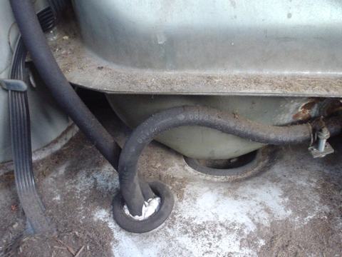
Early 1200s use a simple "loop" vent line that loops to a point high above the tank and exits underneath the fuel tank (outside the body). The loop is to prevent any siphoning effect. Later 1200s vented all the way to the engine compartment (EVAPO models).
The Fuel Cap is a "positive sealing" design which has no pressure relief. EVAPO models have an inlet valve, which is the official replacement for early caps. The inlet valve lets fresh air into the tank, but only for emergency, if the pressure drop is excessive or the vent line is blocked. Normal breathing occurs through the vent line.
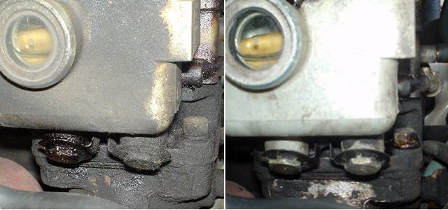
Original and revised (suction relief) Fuel Cap (neither are vented types)
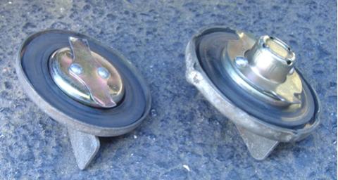
Be sure to use the original 1200 fuel tank cap, which has no pressure vent. If you get occasionally see spilled-fuel staining the car after you drive, you may have the wrong gas tank cap. The cap is Nissan part number 17251-H1900, and was superceded by 17251-H1000, H1901 and H1902.
Carburetors don't need a "fuel return line", and the Datsun 1200 doesn't use one. The low pressure fuel pumps used with carburetors (3 psi) don't need a return line. So the other line going back to the tank is not for "return", but for venting. Later 1200s (1980s models) use a return line to help with emissions.
non-EVAPO
Outside of North America, early 1200 fuel tanks just vented to the air via a hose loop back by the tank. It smells like petrol outside the car. If the windows are rolled up, the fumes should not enter the cabin if the vent line is working correctly. The vent line exits underneath the car, so it's important there are no exposed holes or missing grommets in the body.
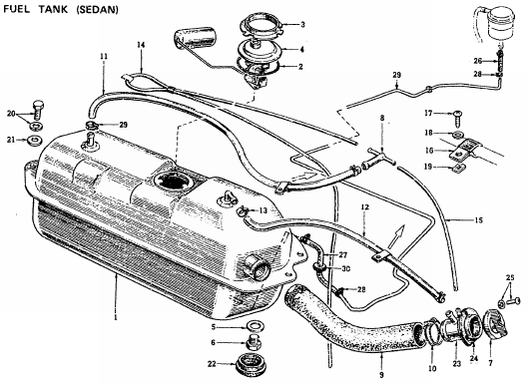
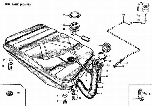
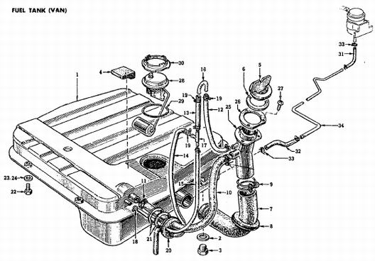
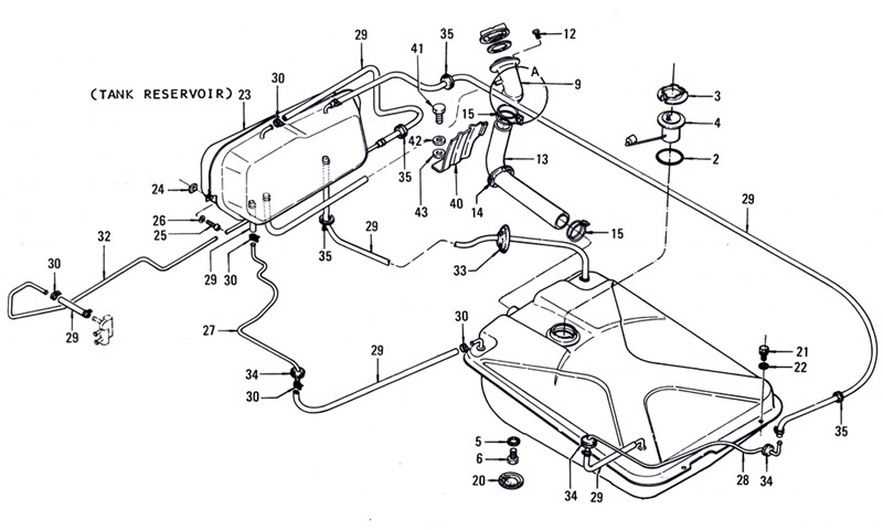
From the JDM parts catalog:
1972 Sedan
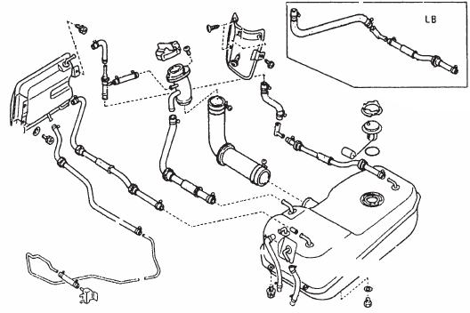
1972 Coupe vents to the filler tube
1972 Wagon vent line loop is more obvious than on the sedan
EVAPO system
#EVAPO is used by all USA 1200s and later Australia and Japan-market 1200 utes.
Flow Guide Valve
7110- North America (1972 models)
1973- Japan B210
Charcoal Canister
7510- Japan B210 (except Van.A12)
The fuel tank filler cap is non-vented, and the smaller of the two hard lines goes to the front of the car, where it is vented.
Coupe
Sunny Truck October 1975
Racing
Evaporative System (Fume Control)
This is a very important system. You want this. Yes, it controls emissions, but it also keeps the carburetor's fuel flow working correctly. It prevents fuel tank fumes from venting directly to the atmosphere. Result = happy planet. But more importantly, on a 1200 EVAPO it is the way the fuel tank breathes. Blocking the hoses would be a bad idea.
EVAPO is used by all USA 1200s and later Australia and Japan-market 1200 utes.
Flow Guide Valve
7110- North America (1972 models)
1973- Japan B210
Charcoal Canister
7510- Japan B210 (except Van.A12)
The fuel tank filler cap is non-vented, and the smaller of the two hard lines goes to the front of the car, where it is #vented.
1972 USA Owners manual (Page 31 ... 31):
 This system prevents gases from going out from the fuel tank into the atmosphere.

System Overview
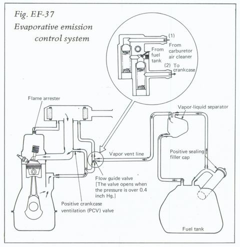
Basically, the fuel tank vapors are vented to the engine crankcase. The four basic parts are:
- Tank with positive-seal filler cap
- Vapor separator (mini tank for exansion gases)
- Vapor vent line
- Flow guide valve
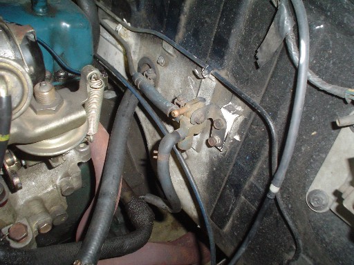
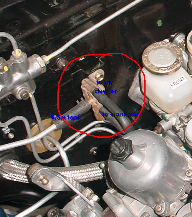
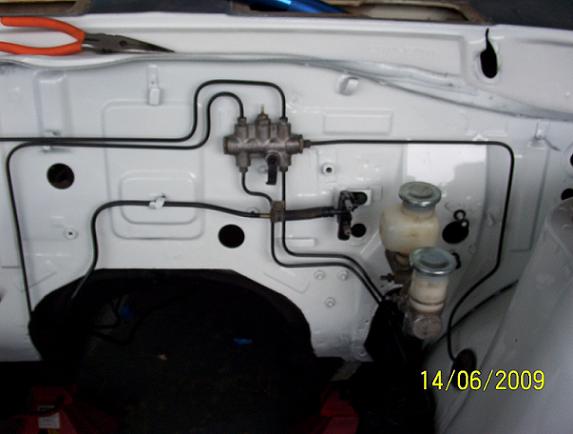
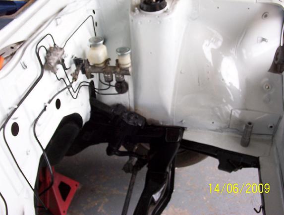
The Flow Guide Valve is located on the firewall, as seen here on a RHD (right hand drive) 1200:
The Flow Guide Valve does the following:
- Guides fresh air (from the air cleaner) into the tank
- Guides tank vapors into the crankcase which serves as an expansion storage tank
- Prevents backflow
Comments
- 1200s used a working, but unrefined system. North American models 1975-up added a Carbon Canister to 'store' the fumes. This is a much better system, and could be retrofitted to the B110.
Discussions about fumes (if you have questions, feel free to continue the discussions):
- POST Fumes
- POST How do i get rid of my fumes in my CAR!!
- POST I still get fumes in the cabin
- mystery part
- POST fuel tank not venting
Charcoal Canister
Some later 1200s and other Sunnys (B210 & B310) used a charcoal canister bolted to left strut tower. This is what most modern automobiles use to contain and filter the fumes. Instead if a Flow Guide Valve, the fuel tank is vented to the canister.
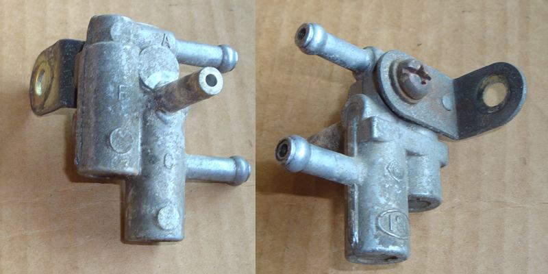
Flow Guide Valve Operation
This part which is bolted to the firewall with the three hose connections is called the "Flow Guide Valve". It controls the flow of fresh air into the tank, and vapors out of the tank.
If the pressure drops in the tank, the one-way valve inside the Guide allows the tank to breathe in. It 'guides' air from the air cleaner into the tank. This happens during normal usage as fuel is used and the fuel level drops. It also occurs due to temperature as the fuel level expands and contracts slightly. Lastly if you drive into the mountains, the air pressure drops. Under all conditions, the valve allows the tank to 'breathe'.
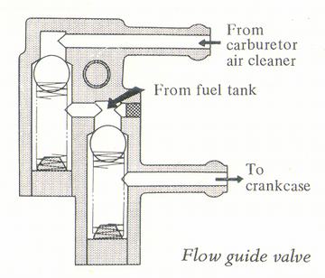
As pressure rises in the tank, whether due to natural vapor loss, or while filling the tank at the gas station, the valve 'guides' vapors into the engine crankcase, thus preventing them from escaping into the atmosphere. This prevents the vapors from entering the cabin of the vehicle. Who wants smelly fumes in the car? In the same way, it keeps the earth smelling better. 90% of a car's pollution used to come from the fuel tank vapors. The good news is that with an evaporative control system like the 1200, the majority of that pollution is prevented.
Operation
The Flow Guide Valve is located on the firewall and:
- Guides fresh air (from the air cleaner) into the tank
- Guides tank vapors into the crankcase which serves as an expansion storage tank
- Prevents a reverse flow of the above via two one-way check valves
- Prevents engine blow-by from entering the fuel tank, thus preventing dangerous backfires
- Prevents fuel tank vapor from escaping into the carb air cleaner
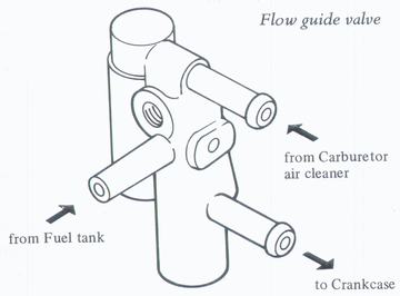
Flow guide valve
- The side port is from the fuel tank. This lets the tank breathe
- The lower outlet (connected in the pic) goes to the crankcase, to the large pipe at back of engine (visible in pic). The fuel fumes are allowed to exand into the crankcase, but not to escape into the atmosphere.
- The top inlet (not connected in the pic) goes to the air cleaner. This lets fresh air into the tank
When the valve operates during various conditions
- When the engine is not running:
- the vapor vent line, liquid separator, and fuel tank are filled with gasoline vapor. When the gaseous vapor rises above 100 mm Hg, the valve opens to pass the flow into the crankcase, where it accumulates
- When the engine is started:
- vapor in the crankcase, manifold and carb air cleaner is sucked into the manifold both through the carb itself and through the PCV valve, where it is burned
- At any time, when the fuel level in the tank drops:
- the guide valve opens to let fresh air flow from the air cleaner into the tank
Flow Guide Valve bolts on firewall to left of engine -- next to brake master cylinder (LHD)
Troubleshooting Fuel Leaks and Smells
Connections
- Make sure all the hoses are connected, and are connected in the correct order (refer to the diagrams above)
- Carefully inspect all the rubber lines to ensure they are not cracked anywhere (it is most common to crack near the ends). Replace any damaged lines.
- Make sure the hose between the rocker cover and the underside of air cleaner is in place and not cracked. Otherwise, fumes go right from the engine, up the firewall and into the outside cowl vents into the passenger compartment
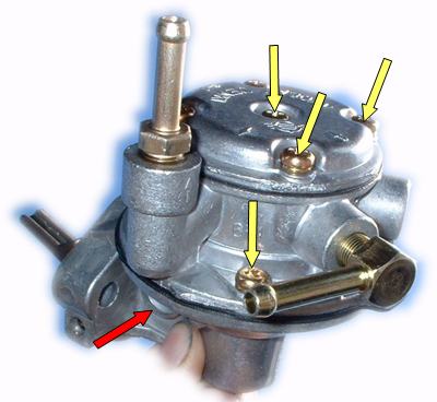
Fuel Pump
Leaking gasket on the Fuel Pump will definitely cause a fuel smell. Finger-tighten these bolts in case they are loose:
Vent Line
- Disconnect the fuel tank vent line from the Flow Guide Valve. Blow through the vent line with a piece of tubing. If you use your mouth, you'll be able to tell if the line is clogged or partially clogged. If it is clogged, undo the connection back at the tank. If it is still blocked, you can try compressed air. If all else fails, replace this steel line
Flow Guide Valve
- Blow (with your mouth, low pressure) through the three ports on the valve, ensuring that the flow only goes in the direction shown in the diagram. If it goes in other directions, spray carb cleaner through it to free the check balls. Sometimes soaking it in a cup of carburetor cleaner will work. If it won't clean up, replace the valve
-
Fuel filler cap
Test the cap's "vacuum relief valve" using a large hose, like clean heater hose.
- Put the tube on the backside of the cap, and blow through the holes in the cap. It should block air.
- inhale, it should let the air go through, perhaps after an initial resistance
If the cap lets air flow each way, replace it with a genuine 1200 cap. Likewise, if it doesn't breath in in means the valve is stuck, replace the cap.
Body Leaks
Fumes can enter the passenger compartment if the body has holes in it.
- Ensure the body is sealed at the firewall plugs
- Ensure the body is sealed near the fuel tank
-
- Body seal at fuel tank
- Fuel line leaks: Carefully inspect and fix any leaks in the fuel line. Even a slow leak can cause a lot of 'gasoline smell'. If you touch the hose and get petrol smell on your finger, it's time to fix it. Even a spot of fuel seeping can cause smell inside the cabin. Especially inspect:
- Fuel filter connections
- Fuel pump connections
- Carburetor fuel line connections
- Carb gaskets
- Carb main jet plugs
-
- Hose connections under body
More details and procedure for checking with a pressure gauge are in the Nissan factory Datsun 1200 "Chassis and Body" Repair Manual. Other manuals also cover this (Chilton, Clymer, Gregory's, Autobook, etc).
Part Numbers
14910-H3902 ASSY-VALVE,FLOW GUIDE 0972-
 14910-H3901
  14910-H3900 1071-
14910-A5502
 14910-A5500, 14910-A5500
14910-A5502 ASSY-VALVE,FLOW GUIDE 510 [1970-up models]
 14910-A5501
 14910-N2200, 14910-N2201, 14910-N2202, 14910-N2203