![[Datsun 1200 encyclopedia]](/wiki/upload/wiki.png)
| Revision as of 08:59, 12 July 2016 ddgonzal (Talk | contribs) <- Previous diff |
Revision as of 00:30, 1 August 2016 ddgonzal (Talk | contribs) (->Horn Button) Next diff -> |
||
| Line 8: | Line 8: | ||
| No. 3: horn relay | No. 3: horn relay | ||
| <br>[http://datsun1200.com/modules/myalbum/photo.php?lid=14969 http://datsun1200.com/modules/myalbum/photos/14969.jpg] | <br>[http://datsun1200.com/modules/myalbum/photo.php?lid=14969 http://datsun1200.com/modules/myalbum/photos/14969.jpg] | ||
| + | |||
| + | = Horn Button = | ||
| + | The horn contact is part of the [[Turn Signals#Switch|turn signal switch]]. If this tab is bent, or electrically burned, the horn won't work. Ditto if the T/S switch is loose. | ||
| + | |||
| + | {{UploadPost|174_579e94be04978.jpg|480279}} | ||
| + | |||
| + | The horn contact touches the underside of the [[Steering wheel]]. If this outer ring improperly lubricated. the horn can have intermittent problems. | ||
| + | |||
| + | {{Photo|gxr3.jpg}} {{Photo|gxr4.jpg}} | ||
| = Wiring = | = Wiring = | ||
Revision as of 00:30, 1 August 2016
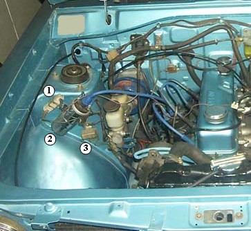
Datsun 1200 used dual horns (Japan STD models used a single horn). The horn system uses a three-connector relay, which is bolted to the right-side strut tower just below the ignition coil.
Contents |
Location
The horn relay is bolted to the right strut tower, under the coil.
The horn(s) are bolted to the radiator Core Support panel.
No. 3: horn relay
Horn Button
The horn contact is part of the turn signal switch. If this tab is bent, or electrically burned, the horn won't work. Ditto if the T/S switch is loose.
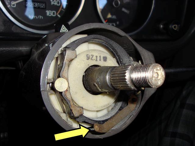
The horn contact touches the underside of the Steering wheel. If this outer ring improperly lubricated. the horn can have intermittent problems.


Wiring
Horn wiring schematic:
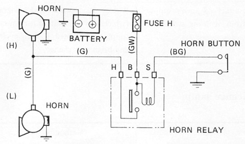
- Fuse 'H' is in the Fuse Box
- + battery voltage is supplied by the horn relay. The horn button switch earths the relay, causing it in turn to supply voltage to the horn. As the horn is a high amperage device, this keeps the power wires out of the steering wheel
- Earth (ground) for the horn is just the fact that it's bolted to the core support panel
- Earth for the horn button goes through the steering wheel hub, which is bolted to the steering gearbox shaft, so it is earthed via the metal of the steering column/gearbox.
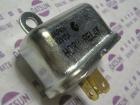
Relay Wire Colors

* Green: to horns
* Green/white: to 15A fuse in fuse box, Battery side
* Black/green: to steering column connector (for horn button)
* Case bolts to body (earth/ground)
Early Relay

Stamped on the relay case are:
* H - connector for Horns
* B - connector for Battery (through fuse box)
* S - connector for Switch (in steering wheel)
Stamped on the relay case are:
* H - connector for Horns
* B - connector for Battery (through fuse box)
* S - connector for Switch (in steering wheel)
Late Relay 26321-G1600 7510-
Part Numbers
26310-H1000 ASS'Y-HORN, high ALL (exc. Coupe)
26310-H1800 ASS'Y-HORN, high, sports Coupe, GX
26330-H1000 ASS'Y-HORN, low DX (exc. Coupe)
26330-H1800 ASS'Y-HORN, low, sports Coupe, GX
26320-14800 RELAY-horn
* 83-10510-14 SCREW (fixing horn relay)