![[Datsun 1200 encyclopedia]](/wiki/upload/wiki.png)
Nissan Factory service manual for the A14E fuel injected engine, 1978 edition.
A14E Service Manual
A14E Service Manual Part 2 Engine Overhaul & Service Data
You can help us out! If you can type Japanese, please click Edit and type in the text. Also need help translating. Thanks!
 |
A型 エンジン
|
A-series Engine
(1978 Standards Conforming Car)
|
目次 Table of Contents
Introduction
はじめに
Introduction
page 1 #English
本書は、NAPS関連装置、EGI装置の点検、整備はもとより、定期点検整備から、車載上におけるエンジンの一般整備、エンジン本体のオーバーホールまで順を追って記載してありますので、日常の一般整備から、定期点検整備まで幅広くご活用ください。
特に、A系エンジンにおいてEGI装置の採用は初めてであり、従来のキャブレーター仕様エンジンと比較して、構造、機能及び点検、整備作業は大幅に変っております。
お客様に十分満足していただくためにも、本書を熟読され、正確、迅速なサービス活動に当られますようお願いいたします。
昭 和 53年 4 月
日産自動車株式会社
サ ー ビ ス 部
This book is a compilation of the inspection and maintenance procedures for A-series EGI engines that use NAPS that conforms to the 1978 emission regulations, compiled as the "A-series Engine Maintenance Procedures Manual [A14-type EGI specification] (for vehicles conforming to the 1978 regulations)".
This book not only describes the inspection and maintenance of NAPS-related devices and EGI devices, but also provides step-by-step instructions for regular inspection and maintenance, general maintenance of the engine on board, and overhaul of the engine itself, so please use it for a wide range of purposes, from daily general maintenance to regular inspection and maintenance.
In particular, this is the first time that an EGI device has been adopted for an A-series engine, and compared to conventional carburetor-equipped engines, the structure, function, inspection, and maintenance procedures have changed significantly.
In order to ensure full customer satisfaction, please read this manual carefully and carry out accurate and prompt service activities.
April 1978
Nissan Motor Co., Ltd.
Service Department
Overview 4
1. 概要
Overview
 | 1. 概要 | 1. Overview
|
排出ガス清浄化システム"NAPS"及びEGI装置は基本的に次の装置で構成され、53年度排出ガス規制に適合している。
1. エンジン改良(エンジン本体、点火系)
2. EGI装置(吸入空気量検出方式)
3. 排気ガス還流(EGR)装置(負荷比例式〔VVT方式〕)
4. 酸化触媒装置(触媒ペレットの改良)
5. 二次空気導入(EAI)装置
The A-series EGI engine, which complies with the 1978 exhaust gas regulations, is based on the conventional engine, but in addition to complying with the 1978 exhaust gas regulations, it also features an improved oxidation catalytic system with improvements to the engine body and the EGI device and various NAPS devices to improve drivability and fuel economy.
The exhaust gas purification system "NAPS" and EGI device are basically composed of the following devices, and comply with the 1978 exhaust gas regulations.
1. Engine improvements (engine body, ignition system)
2. EGI device (intake air volume detection method)
3. Exhaust gas recirculation (EGR) device (load proportional type [VVT method])
4. Oxidation catalyst device (improvement of catalyst pellets)
5. Secondary air introduction (EAI) device
Engine Main Specifications 5
1-1 エンジン主要諸元 Engine Main Specifications
page 5
NAPS Specification List 6
1-2 NAPS仕様-覧 NAPS Specification - List
page 6
Engine Appearance 7
1-3 エンジン外観
Engine Appearance
page 7,8,9


(1) Secondary air intake tube 二次空気導入チューブ
(2) Throttle chamber          スロットル チャンバー
(3) Air regulator             エア レギュレーター
(4) EGR control valve         EGRコントロール バルブ
(5) Dashpot                   ダッシュ ポット
page 8
(1) Water temperature switch 水温スイッチ
(2) TV valve                 TVバルブ
(3) Water temp sensor        水温センサー
(4) Blowby lower hose        プローパイ ホース ロア
page 9
(1) Alternator         オルタネーター
(2) Distributor        ディストリビューター
(3) Blowby upper hose  ブローバイ アッパー ホース
(4) Pressure Regulator プレッシャー レギュレーター
(5) VVT valve          VVTバルブ
(6) VC solenoid valve  VCソレノイド バルブ
(7) Fuel injectors     フューエル インジェクター
Engine Sectional View 10
1-4 エンジン断面図
Engine Sectional View
page 10
Engine Performance Curve 11
1-5 エンジン性能曲線
Engine Performance Curve
page 11
NAPS System View 12
1-6 NAPSシステム図
NAPS System View
page 12
NAPS Piping Diagram 13
1-7 NAPS配管図
NAPS Piping Diagram
(1) Vacuum Hose Diagram
page 13

    mm
 1. 170 Vacuum gallery ~ pressure regulator
 2.  90 VVT tube ~ VVT valve
 3. 200 VVT valve ~ TV valve 3-way connector
 4.  70 Vacuum gallery ~ Dist. 3-way connector
 5.  50 Vacuum gallery ~ Dist. 3-way connector
 6. 190 Vacuum gallery ~ TV valve
 7. 170 EGR control valve ~ TV valve
 8. 110 TV valve ~ 3-way connector
 9. 540 Distributor ~ 3-way connector
10. 120 Vacuum gallery ~ VC solenoid valve
11. 200 VVT valve ~ VC solenoid valve
12. 200 Throttle chamber ~ vacuum gallery
13.  90 Vacuum connector ~ vacuum gallery
14. 130 Throttle chamber ~ vacuum gallery
        (for Distributor)
15. 230 Throttle chamber ~ VC solenoid valve
16. 170 Throttle chamber ~ vacuum gallery
        (for EGR control)
17.     Blind Cap
page 14
Engine Maintenance Notes 15
1-8 エンジン整備上の注意
Engine Maintenance Notes
page 15
page 16
page 17
Engine Start-up Notes 18
1-9 エンジン始動上の注意
Cautions for starting the engine
page 18 #English
エンジンの始動方法を問診し、正しい始動方法をユーザーに指導してください。
(1) ハンド ブレーキ レバーをいっぱいに引き、変速機のシフト レバーをニュートラル位置にする。
(2) アクセル ペダルを踏まないで、スターターを回して始動す。
注意:スターターは連続10秒以上回さない。一度回した後は、10秒以上待ってバッテリーを回復させる。
(3) 始動後、暖機運転をする。
注意:
1.始動直後など、エンジンが冷えている場合、無用の空吹しや高回転にしない。
2.暖機されているときでも、停車中に長時間(10分以上)高回転にしない。
(4) エンジン始動後、バッテリー ターミナルは絶対に外さない。
Ask the user how to start the engine and instruct them on the correct method.
(1) Pull the handbrake lever all the way in and put the transmission shift lever in neutral.
(2) Turn the starter to start the engine without depressing the accelerator pedal.
Caution: Do not turn the starter for more than 10 seconds continuously. After turning it once, wait 10 seconds or more to allow the battery to recover.
(3) After starting, warm up the engine.
CAUTION:
1. When the engine is cold, such as immediately after starting, do not rev the engine unnecessarily or run it at high speed.
2. Even if the engine has been warmed up, do not run it at high speed for long periods of time (more than 10 minutes) while the vehicle is stopped.
(4) After starting the engine, never disconnect the battery terminals.
Regular Inspection And Maintenance 19
2. 定期点検整備 Regular inspection and maintenance
page 19
page 20
page 21
page 22
page 23
page 24
キャニスター Canister
* ?
* ? filter
40,000 km
キャニスター本体 Canister Body
フィルター Filter

フィルターの点検 Filter Inspection
page 25
page 26
page 27
Checker 28
3. チェッカー Checker
Function Checker 28
3-1 ファンクション チェッカー Function Checker
page 28
page 29
EGI Harness Check 30
3-2 EGI ハーネス チェッカー (EG1131) EGI Harness Checker
page 30
(1) (2)page 31
page 31
page 32
page 33
page 34 - EGI Circuit

 full | japanese
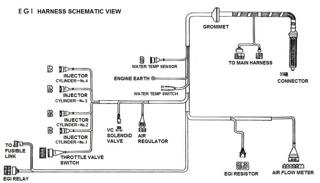
Page 35 - Checker: ハーネス実態図 EGI Harness Schematic View

 full | Japanese
page 36
page 37
EGI Control Unit Checker 38
3-3 EGIコントロール ユニット チェッカー EGI Control Unit Checker
page 38
page 39
page 40
page 41
Fault Diagnosis 42
4. 故障診断 Fault diagnosis
page 42
page 43
page 44
On-vehicle Engine Maintenance 45
5.
車載上のエンジン整備
On-board engine maintenance
5-1 Idle Adjustment 45
5-2 Air Cleaner and EAI 48
5-3 EFI 52
5-4 Decel Device 71
5-5 EGR 72
5-6 Air-fuel ratio and EGR switching 77
5-7 Ignition System 82
5-8 Throttle Chamber 89
5-9 Manifold 90
5-10 Cylinder Head 92
5-11 Catalytic Converter 95
5-12 EVAPO 103
5-13 PCV 104
5-14 Lubrication System 105
5-15 Cooling System 108
Engine Removal and Installation 111
エンジン脱着
Removing and installing the engine
6. エ ン ジ ン 脱 着
Removing and installing the engine
page 111
page 112
page 113
Engine Overhaul 114
7 Engine Overhaul 114 7.1 Overhaul Notes 114
7.2 Disassembly 115
7.3 Inspection, Correction, Replacement 119 7.3.1 Cylinder Head and Valve 119
7.3.2 Cylinder Block 124
7.3.3 Piston, Piston Ring, Conrod 125
7.3.4 Crankshaft, Main Bearing 128
7.3.5 Camshaft 130
7.3.6 Other Components 131
7.4 Assembly 132
Service Data 141
8. サ=ビス データ Service Data
See A14E Service Manual Part 2
8.1 Standard Bolt, Nut Tightening Torque 141
8.2 Engine Torque Specs 142
8.3 Service Data 143
Special Tools And Checker 146
9. 特殊工具監及びチェッカー Special tools and checker
Special Tools 146
9-1 特殊工具
page 146
page 147
page 148
page 149
page 150
Checker and Check Sheet 151
9-2 チェッカー及びチェック シート
page 151
page 152
page 153
page 154
Inspection Circuits 155
10. 点検回路 Checking Circuits
Function Checker Check 155
10-1 ファンクション チェッカー チェック
page 155
EGI Harness Checker Check 156
10-2 EGI ハーネス チェッカー チェック
page 156
page 157
page 158
page 159
page 160
page 161
page 162
page 163
page 164
page 165
page 166
page 167
page 168
page 169
page 170
page 171
page 172
page 173
page 174
page 175
Memos 176-182
[pages 176-182 are blank "Memo" pages for taking notes]


Publisher's Page 183
page 183 #English
複製を禁ず
印 刷発行 昭和 53年 4 月
改 訂 昭和 53年 6 月
『複製品』
発行所
日産自動車株式会社
担当
サービス部技術資 料課
東 京 都 中 央 区 銀 座 6-17-1
TEL 03-543-5523
1 H-804055
2 H-806005
3 H-003010
4 H-105013
This book contains instructions for disassembly, assembly, adjustment, etc. of each device. However, since disassembly and maintenance is regulated by a notification from the Ministry of Transport that "disassembly and maintenance must be carried out by persons certified for automobile disassembly and maintenance," we ask that you always ask a maintenance shop to carry out disassembly and maintenance.
Printed April 1978
Revised June 1978
"Reproduction"
Published by
Nissan Motor Co., Ltd.
Contact
Technical Information Section, Service Department
6-17-1 Ginza, Chuo-ku, Tokyo
TEL: 03-543-5523
1 H-804055
2 H-806005
3 H-003010
4 H-105013
Back cover
 | 日産自動車株式会社 | Nissan Motor Co., Ltd. |