![[Datsun 1200 encyclopedia]](/wiki/upload/wiki.png)
<-- back to A14E Service Manual
Nissan Factory service manual for the A14E fuel injected engine, 1978 edition.
A14E Service Manual
A14E Service Manual Part 2 Engine Overhaul & Service Data
You can help us out! If you can type Japanese, please click Edit and type in the text. Also need help translating. Thanks!
 |
A型 エンジン
|
A-series Engine
(1978 Standards Conforming Car)
|
On-vehicle Engine Maintenance 45
5.
車載上のエンジン整備
On-board engine maintenance
Idle Adjustment 45
5-1 アイドル調整
Idle adjustment
#English
page 45 #JP #EN page 46 #JP #EN page 47 #JP #EN


(1) 二次空気カット
- EAIホースを外し、EAIチューブにめくら栓をする。
めくら栓部品番号: 16520 U9600
EAIホースめくら栓
(2) 暖機運転
- 「1-9 エンジン始動上の注意」(P.18) に従い、エンジンを始動する。
- 十分暖機する。
- 注意:
- 1. 暖機運転中、急激なアクセル操作はしないこと。
- 2. 走行直後の車両については、触媒が反応する温度になっている可能性があるため、アイドル状態で5分間程度放置し、触媒の温度を下げてからアイドル調整をする。
- 注意:
(3) 点火時期の調整
- ディストリビューター ダイアフラム側でパキューム ホースを外し、ホースにめくら栓をする。

- エンジンをアイドル状態にし、タイミングライトを用いて、7° BTDCに調整する。
- 注意:
- 1. 調整は調整用ボルトをゆるめ、本体を回して調整する。
- 2. バキューム ホースを外したときの回転数を 700rpm に調整する。
- 注意:
- バキューム ホースを接続し、点火時期が15~25°BTDC の範囲にあることを 確認する。
- 注意:
- 1. ホースを外したときに規定値であって、ホースを接続したとき 15~25° にならない場合は、ホースの詰まりやオリフィスを点検すること。(調整ボルトにより、ディストリビューター本体を回して調整してはいけない。)
- 2. 点火時期調整後、調整用ボルトに封印テープをする。
- 注意:
点火時期  通常時  バキューム カット時
BTDCº    15~25   7
封印テープ部品番号 B2235 U7410

(4) アイ ドル回転数の調整
- スロットル チャンバーのアイドル アジャスト スクリュー(IAS)を回して、規定の回転数に調整する。

アイドル規定回転後
700 rpm
(5) CO、HC 濃度の点検、調整
- CO/HC テスターでアイドルCO、HC濃度を測定する。
アイドル CO/HC 濃度
CO濃度整備目標値(%)    1.5
HC濃度整備目標値(ppm)  800 以下
- 注意:
- (1) CO/HC テスターは取扱説明書をよく読んで正しい操作と点検整備をすること。
- (2) CO/HC テスターは十分暖機してから使用する。

排気ガス濃度測定
- CO濃度が整備目標値にない場合は、エアメーターの調整スクリュー(右図参フロー照)により、調整する。
- 注意: CO濃度の点検、調整の際には、スロットル バルブ スイッチのアイドル接点がONになっていること。(P.64参照)

(6) 二次空気供給
- EAIホースを接続し、元の状態にもどす。
- エンジン回転を約 2, 500rpm にして、約3分間回し触媒温度を上昇させる。
(7) アイドル CO、HC 測定
- CO/HC テスターでCO、HC濃度を測定する。
CO 濃度 (%)     0.5 以下
HC 濃 度 (ppm)  200 以下
(8) アイドル回転数再調整
- アイドル アジャスト スクリュー(IAS)にて、規定の回転数に再度調整する。
5-1 Idle adjustment
(1) Secondary air cut
- Remove the EAI hose and plug the EAI tube.
Blind plug part number: 16520 U9600
EAI hose plug
(2) Warm-up operation
- Start the engine following the instructions in "1-9 Precautions for starting the engine" (p. 18).
- Allow the engine to warm up sufficiently.
- Caution:
- 1. Do not operate the accelerator suddenly while warming up the engine.
- 2. If the vehicle has just been driven, the catalyst may be at a reaction temperature, so leave the vehicle at idle for about 5 minutes to allow the catalyst temperature to drop before adjusting the idle.
- Caution:
(3) Adjusting the ignition timing
- Remove the vacuum hose on the distributor diaphragm side and plug the hose.

- With the engine at idle, use a timing light to adjust to 7° BTDC.
- Note:
- 1. To adjust, loosen the adjustment bolt and turn the main body.
- 2. Adjust the rotation speed to 700 rpm when the vacuum hose is removed.
- Note:
- Connect the vacuum hose and check that the ignition timing is in the range of 15-25°BTDC.
- Caution:
- 1. If the ignition timing is the specified value when the hose is removed and is not 15-25° when the hose is connected, check the hose for clogs and orifices. (Do not adjust by turning the distributor body using the adjustment bolt.)
- 2. After adjusting the ignition timing, apply sealing tape to the adjustment bolt.
- Caution:
Ignition timing Normal  Vacuum cut
BTDCº           15-25   7

Sealing tape part number B2235 U7410
(4) Adjusting the idle speed
- Turn the idle adjustment screw (IAS) in the throttle chamber to adjust the speed to the specified value.

After the specified idle speed
700 rpm
(5) Checking and adjusting CO and HC concentrations
- Measure idle CO and HC concentrations with a CO/HC tester.
Idle CO/HC concentration
CO concentration maintenance target value (%)    1.5
HC concentration maintenance target value (ppm)  800 or less
Caution:
- (1) Carefully read the instruction manual for the CO/HC tester and operate and maintain it correctly.
- (2) Use the CO/HC tester only after the engine has been sufficiently warmed up.
Exhaust gas concentration measurement
- If the CO concentration is not at the target maintenance value, adjust it using the air meter adjustment screw (see flow chart on the right).
- Note: When checking and adjusting the CO concentration, make sure the idle contact of the throttle valve switch is ON. (See page 64)

(6) Secondary air supply
- Connect the EAI hose and return to the original state.
- Set the engine speed to about 2,500 rpm and run it for about 3 minutes to raise the catalyst temperature.
(7) Idle CO and HC measurement
- Measure the CO and HC concentration with a CO/HC tester.
CO concentration (%)    0.5 or less
HC concentration (ppm)  200 or less
(8) Readjust the idle speed
- Readjust the idle speed to the specified speed using the idle adjustment screw (IAS).
Air Cleaner and EAI 48
5-2 エア クリーナー及び二次空気導入(EAI) 装置
Air cleaner and Exhaust Air Induction (EAI) device
page 48
page 49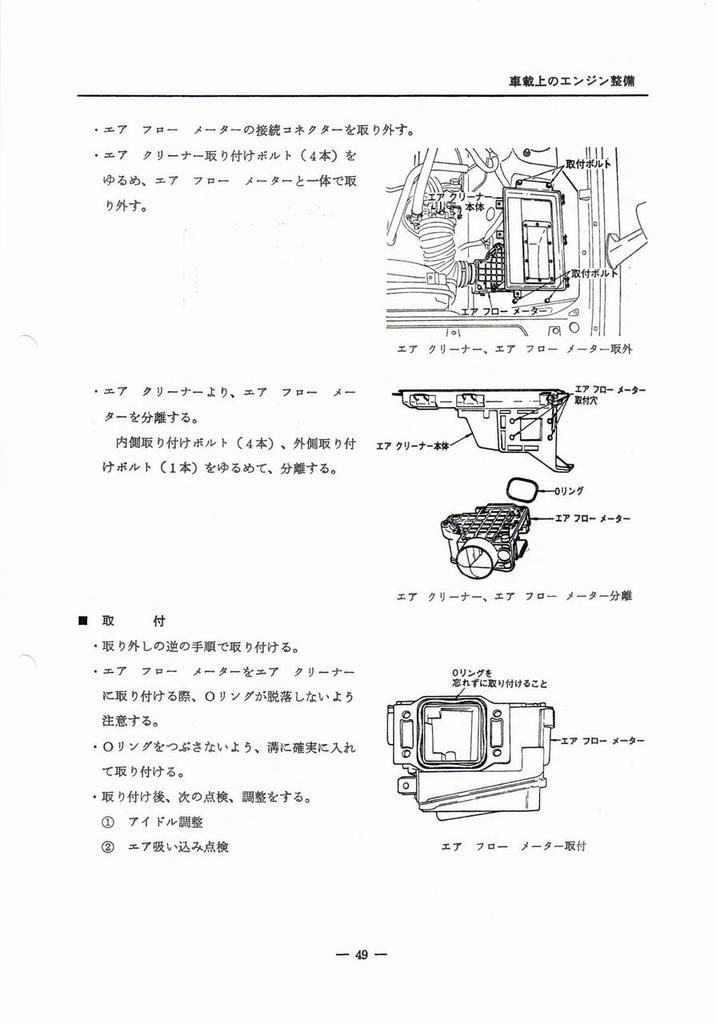
page 50
page 51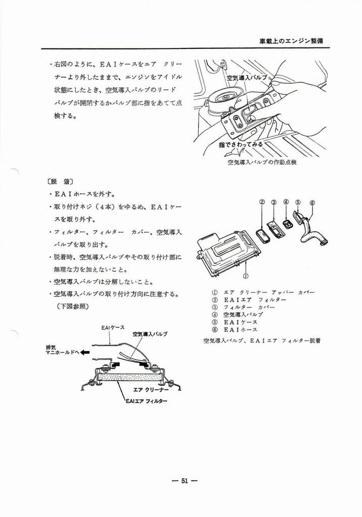
EFI 52
5-3 電子制御燃料噴射装置
Electronically controlled fuel injection system
page 52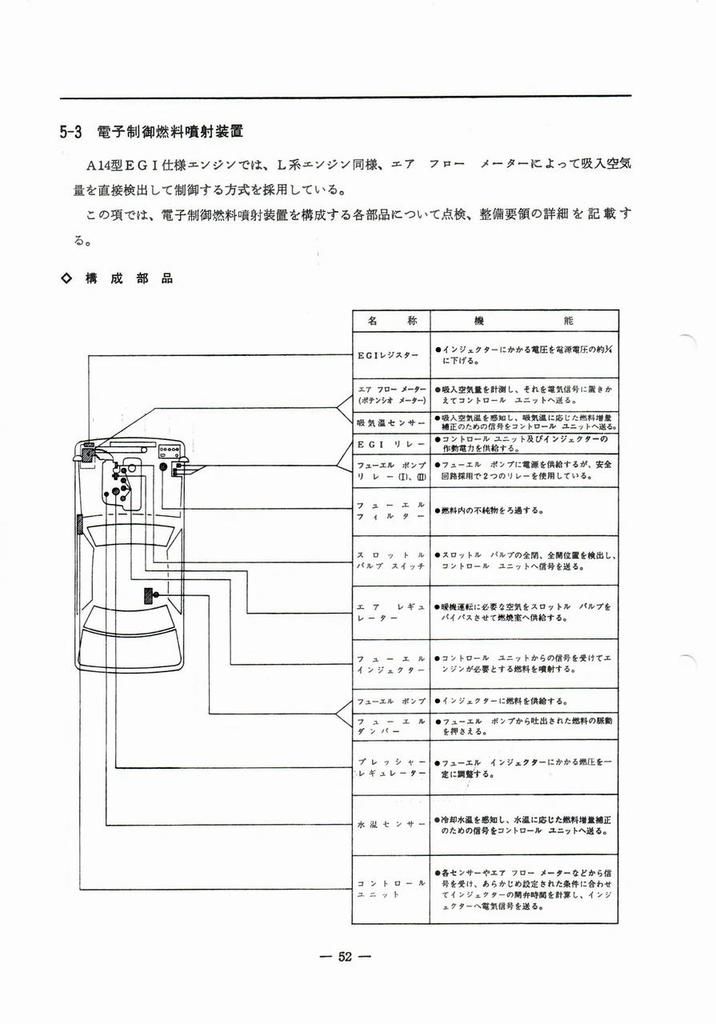
page 52
page 53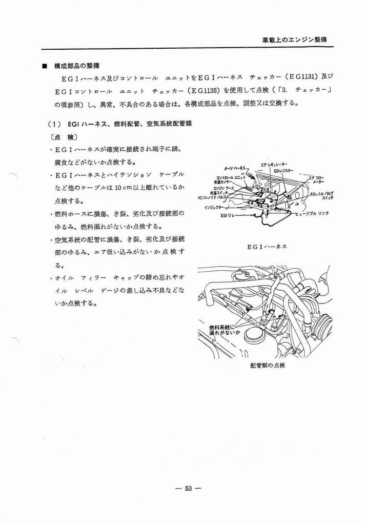
page 54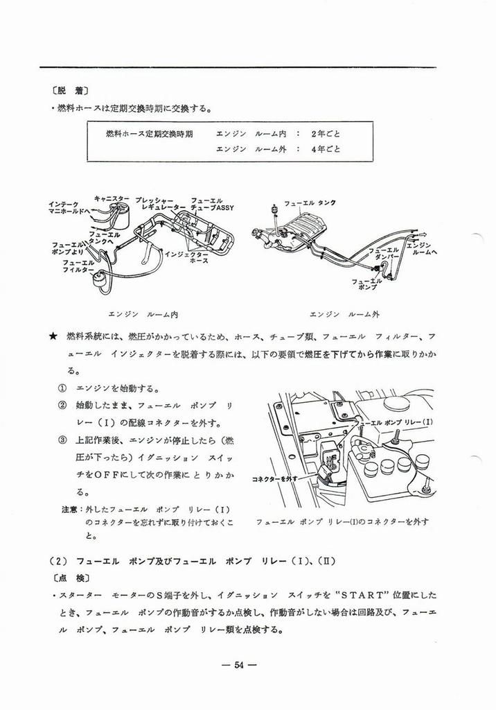
page 55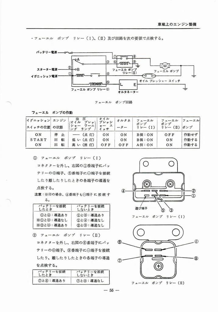
page 56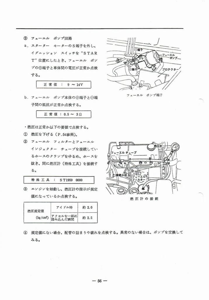
page 57
page 58
page 59
page 60
page 61
page 62
page 63
page 64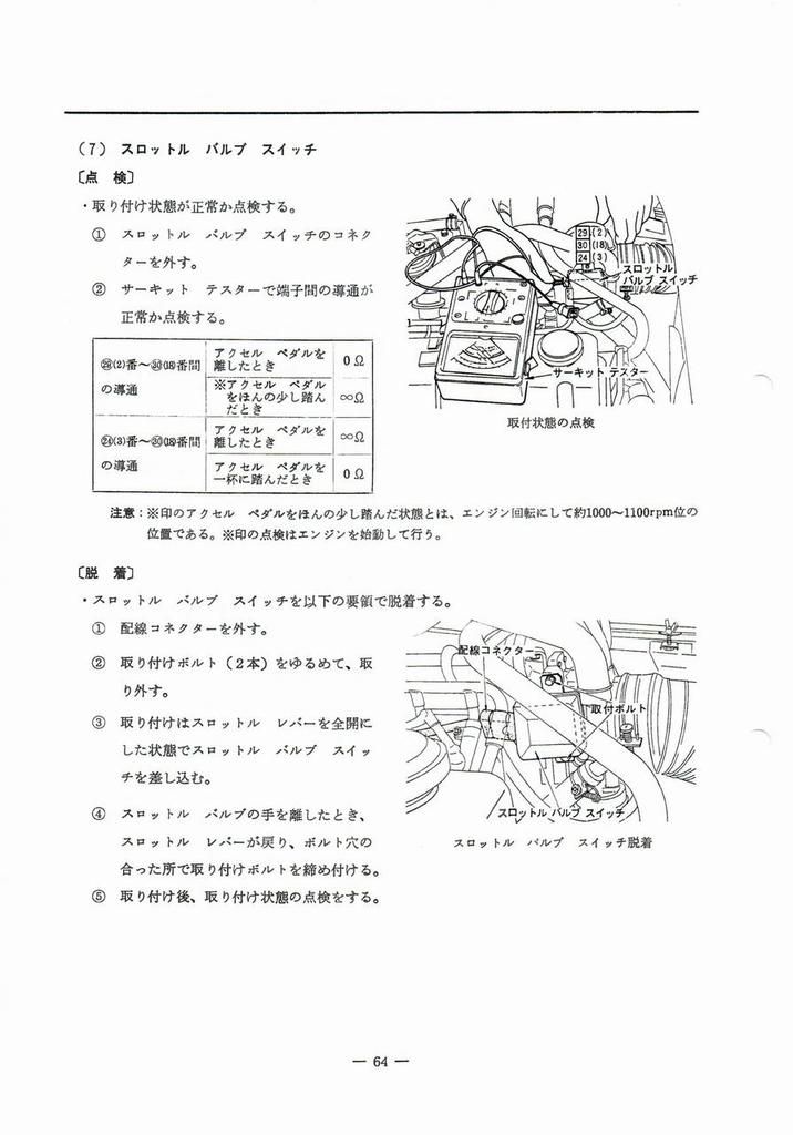
page 65
page 66
page 67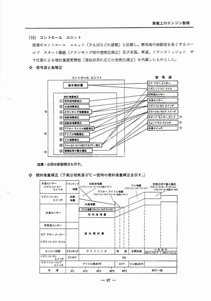
page 68
page 69
page 70
Decel Device 71
5-4 減速時排気ガス減少装置
Deceleration exhaust gas reduction device
page 71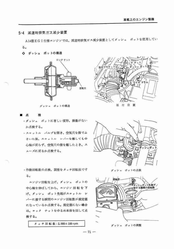
EGR 72
5-5 排気ガス還流(EGR) 装置
Exhaust Gas Recirculation (EGR) System
page 72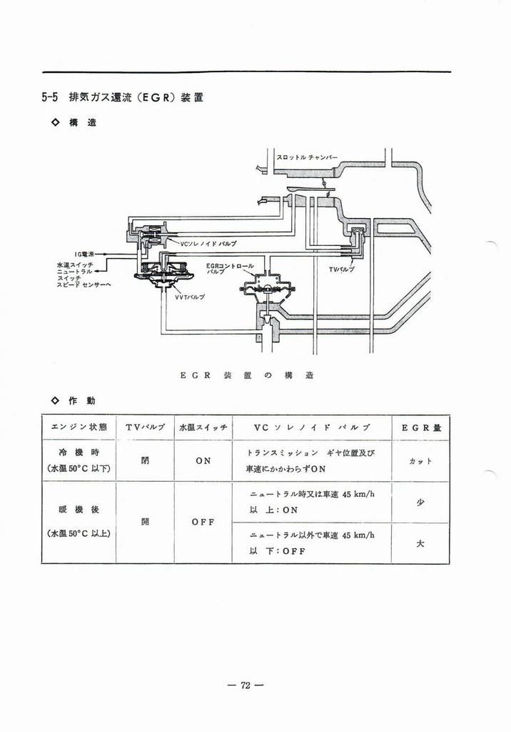
page 73
page 74
page 75
page 76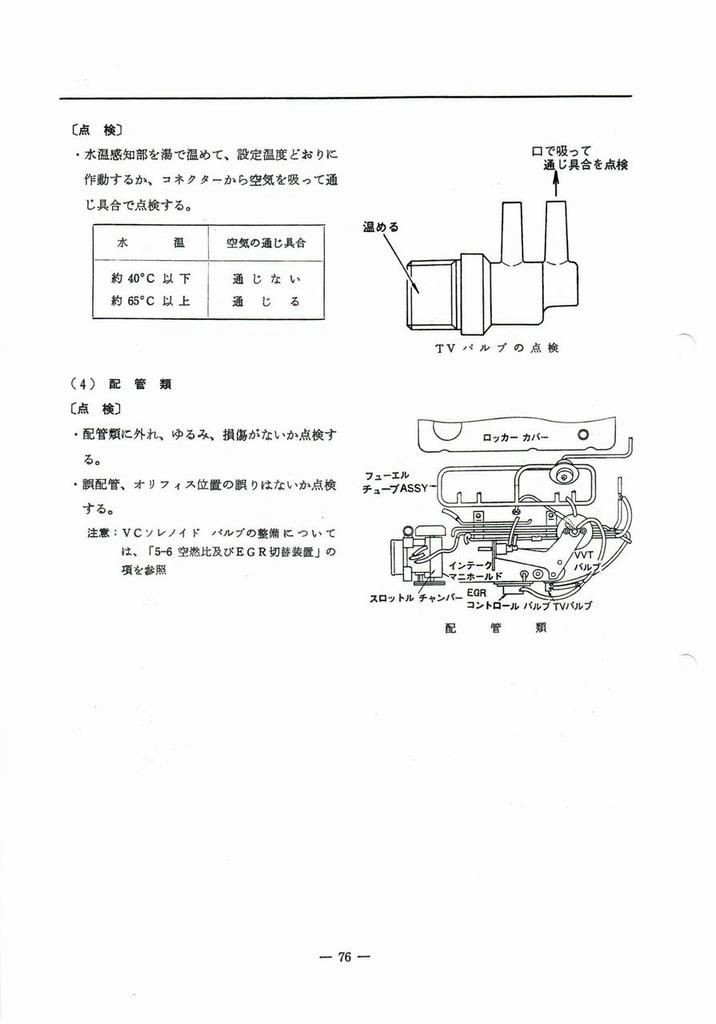
Air-fuel ratio and EGR switching 77
5-6 空燃比及びEGR切替装置
Air-fuel ratio and EGR switching device
page 77 #JP #EN page 78 #JP #EN
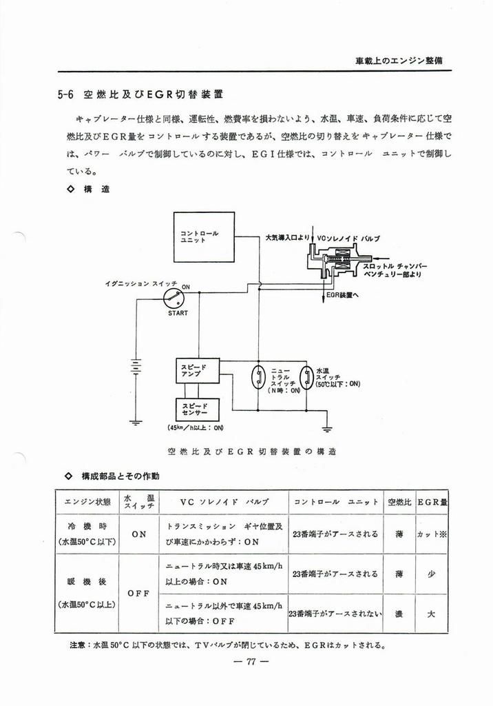
キャブレーター仕様と同様、運転性、燃費率を損わないよう、水温、車速、負荷条件に応じて空燃比及びEGR量をコントロールする装置であるが、空燃比の切り替えを キャブレーター仕様では、パワー バルブで制御しているのに対し、EGI仕様では、コントロール ユニットで制御している。
◇ 構 造

| エンジン状態 | ,水温 スイッチ | ,VC ソレノイド バルブ | ,コントロール ユニット | ,空燃比 | ,EGR불 |
|---|---|---|---|---|---|
| 冷機時 (水温50°C以下) | ,ON | ,トランスミッション ギャ位置及 び車速にかかわらず:ON | ,23番端子がアースされる | ,薄 | ,カット※ |
| 暖機後 (水温50°C以上) | ,OFF | ,ニュートラル時又は車速 45km/h 以上の場合:ON | ,23番端子がアースされる | ,薄 | ,少 |
| , | , | ニュートラル以外で車速 45km/h 以下の場合:OFF | ,23番端子がアースされない | ,濃 | ,大 |

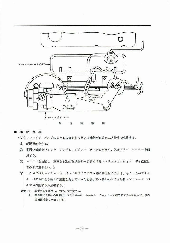
配管実態図
■ 機能点検
- VCソレノイド バルブによりEGRを切り替える機能が正常か二人作業で点検する。
- 暖機運転をする。
- 車両の後部をジャッキ アップし、リジッド ラックをかうか、又はフリー ローラーを使用する。
- エンジンを始動し、車速を60km/h以上の一定速にする(トランスミッション ギャ位置はTOPが望ましい。)
- 一人がEGRコントロール バルブのダイアフラム部に手を当てておき、もう一人がアクセル ペダルにより徐々に速度を落していったとき、50~40km/h でEGRコントロール バルブが作動するか点検する。
- 注意:
- 1. 必ず手袋を使用し、やけどに注意する。
- 2. 空燃比切り替えの機能は、コントロール ユニット チェッカー及びアダプターを用いて、空燃比補正増量の点検をする。
Like the carburetor model, this device controls the air-fuel ratio and EGR volume according to water temperature, vehicle speed, and load conditions so as not to impair drivability or fuel economy. However, whereas the carburetor model controls the air-fuel ratio change with a power valve, the EGI model controls it with a control unit.
◇ Structure

| Engine status | ,Water temperature switch | ,VC solenoid valve | ,Control unit | ,Air-fuel ratio | ,EGR valve |
|---|---|---|---|---|---|
| When cold (water temperature below 50°C) | ,ON | ,Regardless of transmission gear position and vehicle speed: ON | ,Terminal 23 is grounded | ,Light | ,Cut* |
| After warming up (water temperature above 50°C) | ,OFF | ,When in neutral or vehicle speed above 45km/h: ON | ,Terminal 23 is grounded | ,Light | ,Slight |
| , | , | When not in neutral and vehicle speed below 45km/h: OFF | ,Terminal 23 is not grounded | ,Dark | ,High |

PIPING DIAGRAM
■ Functionality check
- Check that the EGR switching function using the VC solenoid valve is working properly with two people.
- Warm up the engine.
- Jack up the rear of the vehicle and use a rigid rack or free rollers.
- Start the engine and keep the vehicle speed at a constant speed of 60km/h or more (the transmission gear position should be in TOP).
- One person places their hand on the diaphragm of the EGR control valve while the other person uses the accelerator pedal to gradually slow down the vehicle. Check that the EGR control valve operates at 50-40km/h.
- Caution:
- 1. Be sure to wear gloves and take care not to get burned.
- 2. Check the air-fuel ratio switching function by using the control unit checker and adapter to check the air-fuel ratio correction increase.
page 79
page 80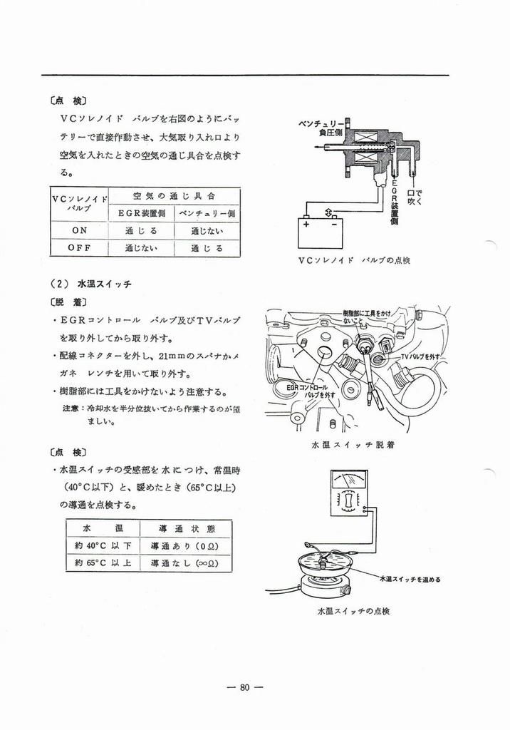
page 81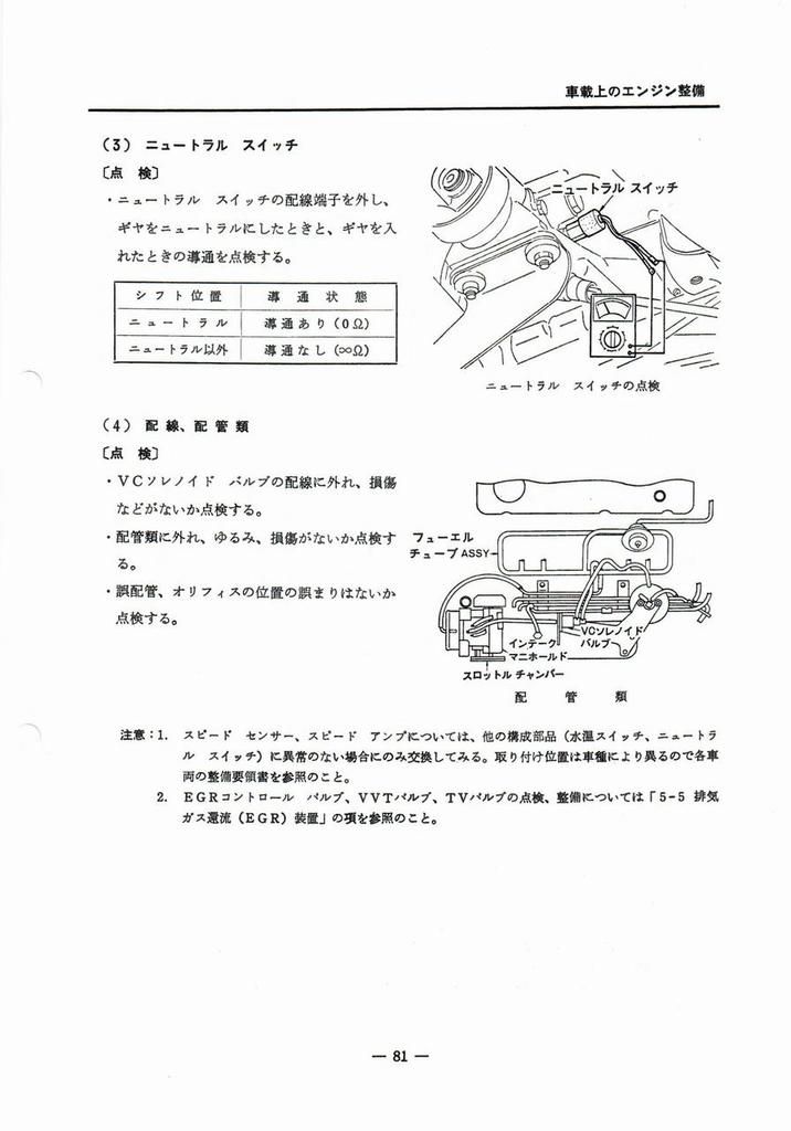
Ignition System 82
5-7 点火装置
Ignition device
page 82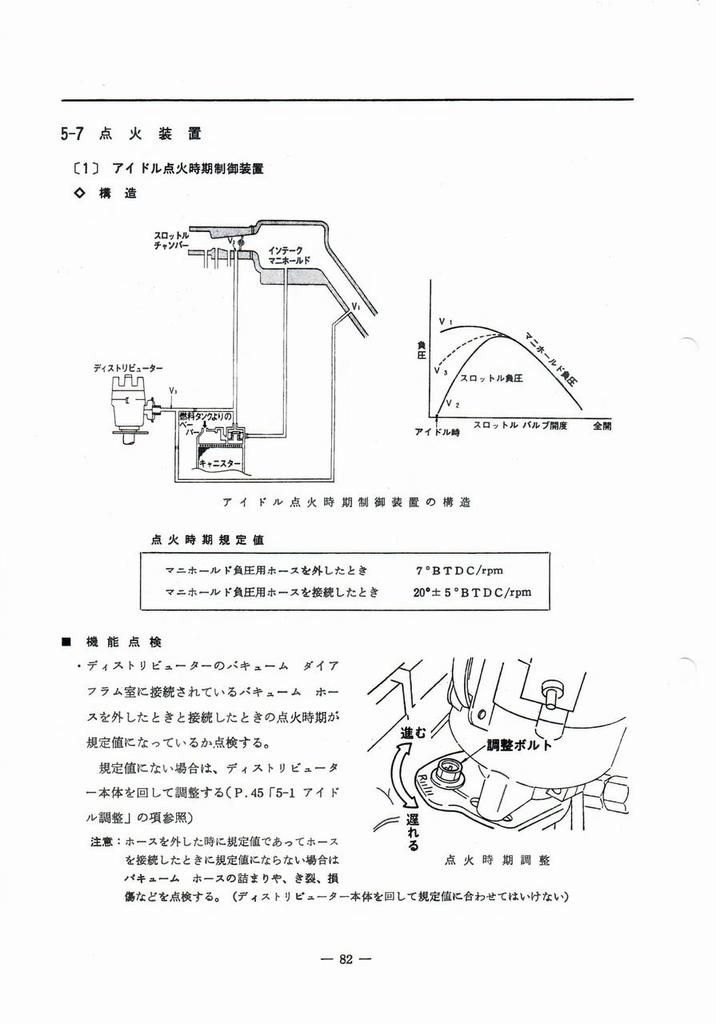
page 83
page 84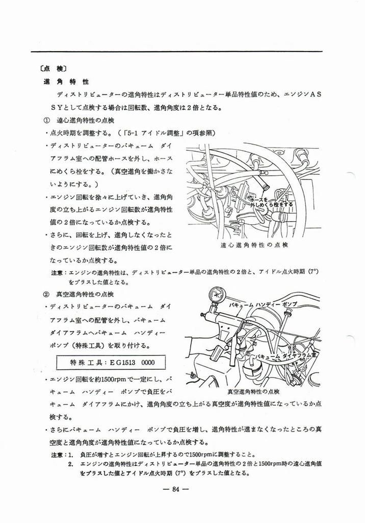
page 85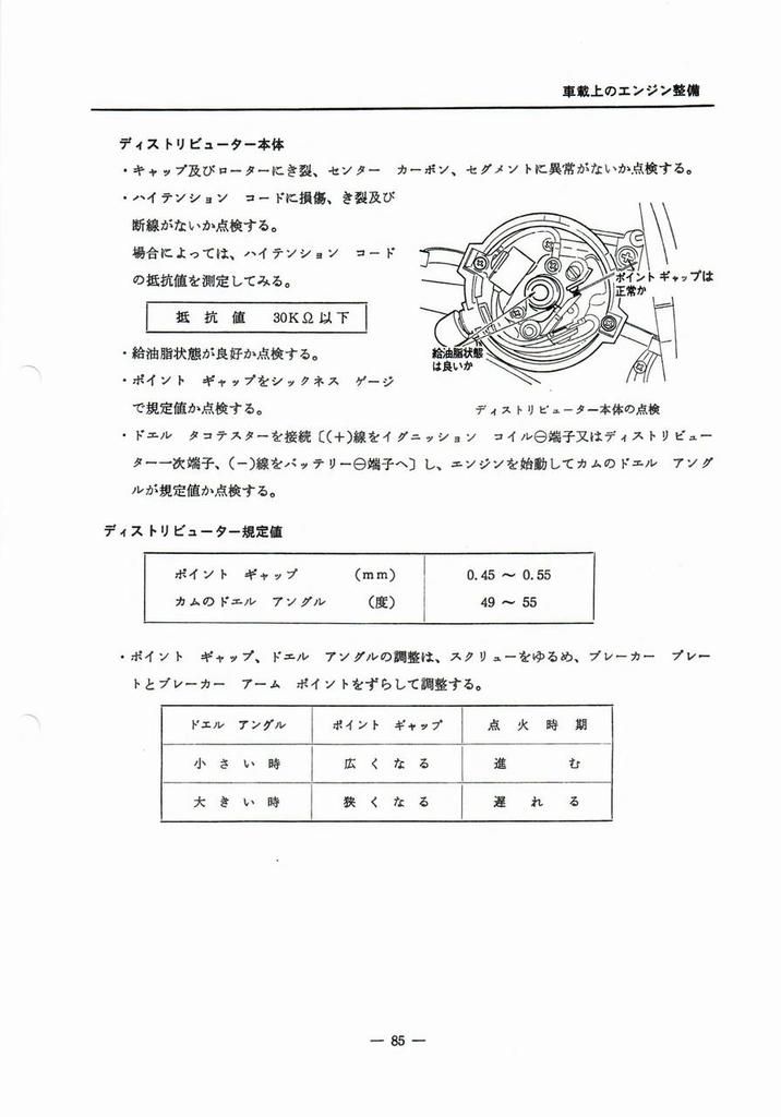
page 86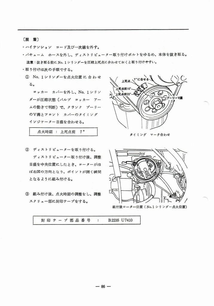
page 87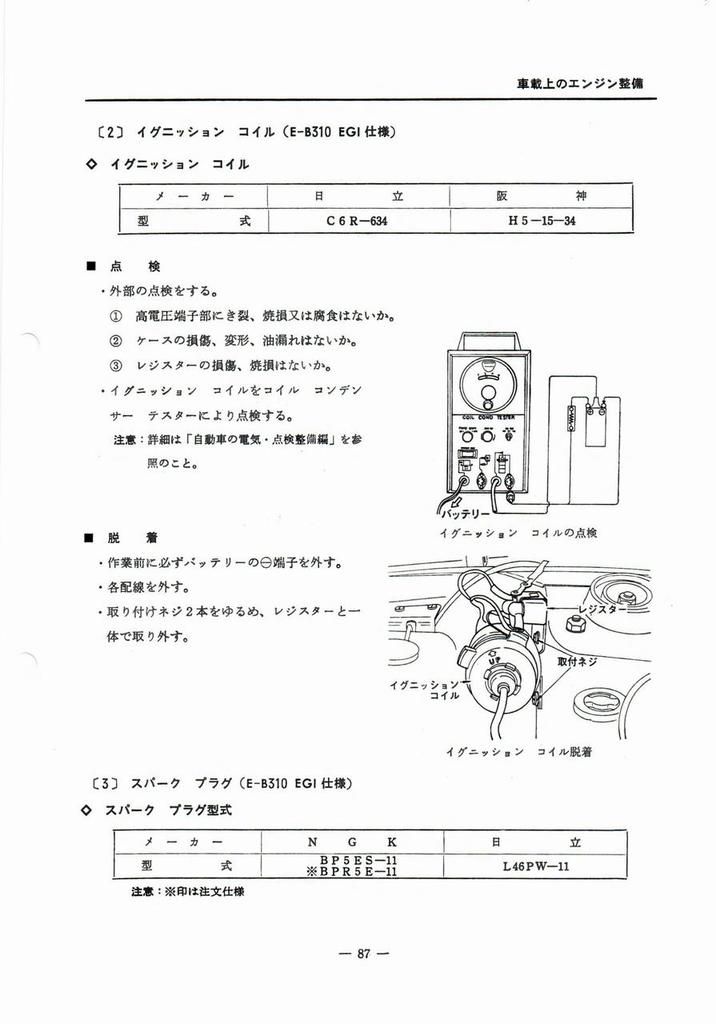
page 88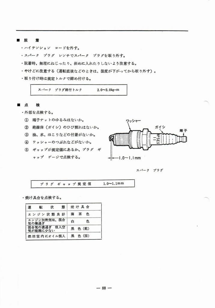
Throttle Chamber 89
5-8 スロットル チャンバー
page 89
Manifold 90
5-9 マニホールド
Manifold
page 90 #English
■ 点検
·取り付けにゆるみがなく、排気漏れ、エアの吸い込み及び水漏れなどがないか点検する。
·取り付けにゆるみのある場合は、増し締めをする。
共締部
マニホールド取付ナット締付順序
締付 トル ク
インテーク マニホールド 2、3、10、11    1.6~2.1kg-m
エキゾースト マニホールド 1、4~7、8、9  1.6~2.1kg-m
   (インテーク マニホールドとの共締部含む)
■ 取外
·燃圧を下げる。(P.54参照)
·エア クリーナーASSYを外す。(エア ダクト ホースと一体で)(P.48参照)
·バッテリーの日端子を外す。
·フューエル チューブASSY (インジェクター共)を取り外す。(P.60参照)
·配線、配管類を外す。
(1) EGIハーネス(エア レギュレーター、水温センサー)
(2) ブローバイ ロア ホース
(3) ディストリビューター用バキューム ホース
(4) 温水用ホース
(5) マスター バック用バキュームホース
(6) キャニスター用バキューム ホース
配線、配管類
■ Inspection
* Check that the installation is tight and that there are no exhaust leaks, air intakes, or water leaks.
* If the installation is loose, tighten it further.
Common fastening parts
Manifold mounting nut tightening sequence
Tightening torque
Intake manifold  2, 3, 10, 11    1.6-2.1kg-m
Exhaust manifold 1, 4-7, 8, 9    1.6-2.1kg-m
 (including common fastening parts with intake manifold)
■ Removal
* Reduce the fuel pressure. (See #page 54)
* Removing the air cleaner assembly (together with the air duct hose) (See #page 48)
* Disconnect the battery terminal.
* Removing the fuel tube assembly (with injectors). (See #page 60)
* Remove the wiring and piping.
(1) EGI harness (air regulator, water temperature sensor)
(2) Blow-by lower hose
(3) Distributor vacuum hose
(4) Hot water hose
(5) Master back vacuum hose
(6) Canister vacuum hose
Wiring and piping
page 91
Cylinder Head 92
5-10 シリダー ヘッド
page 92
page 93
page 94
Catalytic Converter 95
5-11 触媒コンバーター及び排気温度警報装置
Catalytic converter and exhaust temperature warning device
page 95
page 96
page 97
page 98
page 99
page 100
page 101
page 102
EVAPO 103
5-12 燃料蒸発(エバポ) ガス抑止装置
Fuel evaporation (EVAPO) gas suppression device
page 103
PCV 104
5-13 ブローバイ ガス還元装置
Blow-by gas reduction device
page 104
Lubrication System 105
5-14 潤滑装置
Lubricating device
page 105
page 106
page 107
Cooling System 108
5-15 冷却装置
Cooling device
page 108
page 109
page 110
<-- back to A14E Service Manual