![[Datsun 1200 encyclopedia]](/wiki/upload/wiki.png)
<-- back to B210 Options
B210 and PB210 Optional parts installation instructions book (1973) for the Sunny Genuine Option Parts.
Cover
inset: photo of Excellent 1400 Coupe tricked out with option parts

ダットサン サニー 1200 1400エクセレント
B210、PB210系車
オプション部品
取付粟領書
日産自動車式会社
Datsun Sunny 1200 1400 Excellent
B210, PB210 series cars
Optional parts
Installation instructions
Nissan Motor Co., Ltd.
Preface
まえがき
Preface
このたび発表発売致しましたサニーB210型車をさらに豪華萇な車としてユーサーの方々にご満足頂けるよう数多くのオプション部品を設定しました。 本書は、これらのオプション部品のちの主なものの取り付け要領をでご紹介致します。
We have added a number of optional parts to the recently released Sunny B210 model to make it even more luxurious and satisfy users. This book introduces the installation procedures for the main optional parts.
オプション取り付けの実作業に当ってな、本書をで活用されますようお願い申し上げます。
Please make use of this manual when actually installing options.
なお、取り付け時の標準作業時間も記載致しましたのでご利用ください。
Please note that we have also listed the standard working hours for installation.
昭和48年5月
May 1973
日産自動車株式会社
サービス 部
Nissan Motor Co., Ltd.
Service Department
Table of Contents
目次
Table of Contents
フォグ ランプ               3 #Fog Lamps
オーバー ヘッド コンソール         8 #Overhead Console
カー ステレオ              10 #Car Stereo
時 計                  12 #Clock
ラヂオ(AM-FM)              15 #Radio (AM-FM)
カレンダー                16 #Calendar
電流計                  17 #Ammeter
油圧計                  18 #Oil Pressure Gauge
電圧計                  19 #Voltmeter
間歇ワイパー               20 #Intermittent Wipers
スポーツ バイザー            21 #Sport Visor
サイド  バイザー、ルーフ バイザー   21 #Side Visor, Roof Visor
マッド ガード              22 #Mudguard
アクセント ストライプ          22 #Accent Stripe
本木目ステアリング ホイール       22 #Wood Grain Steering Wheel
トラッシュ ボックス           23 #Trash Box
トノカバー                24 #Tonneau Cover
タコメーター(タコ ボルト メーター)  26 #Tachometer (and Tacho-Volt Meter)
トランク リッド オープナー       28 #Trunk Lid Opener
主なオプション部品の配線要領       33 #Wiring procedure of the main options parts
インストルメント下側ユニット取り付け図  34 #Instrument lower unit mounting drawing
主要オプション部品取り付け標準作業時間  巻末 #Main Optional Parts Installation Standard Working Time
巻末
End of book
Fog Lamps
フォグ ランプ
Fog Lamps
取付標準時間 1.0
Installation standard time 1.0
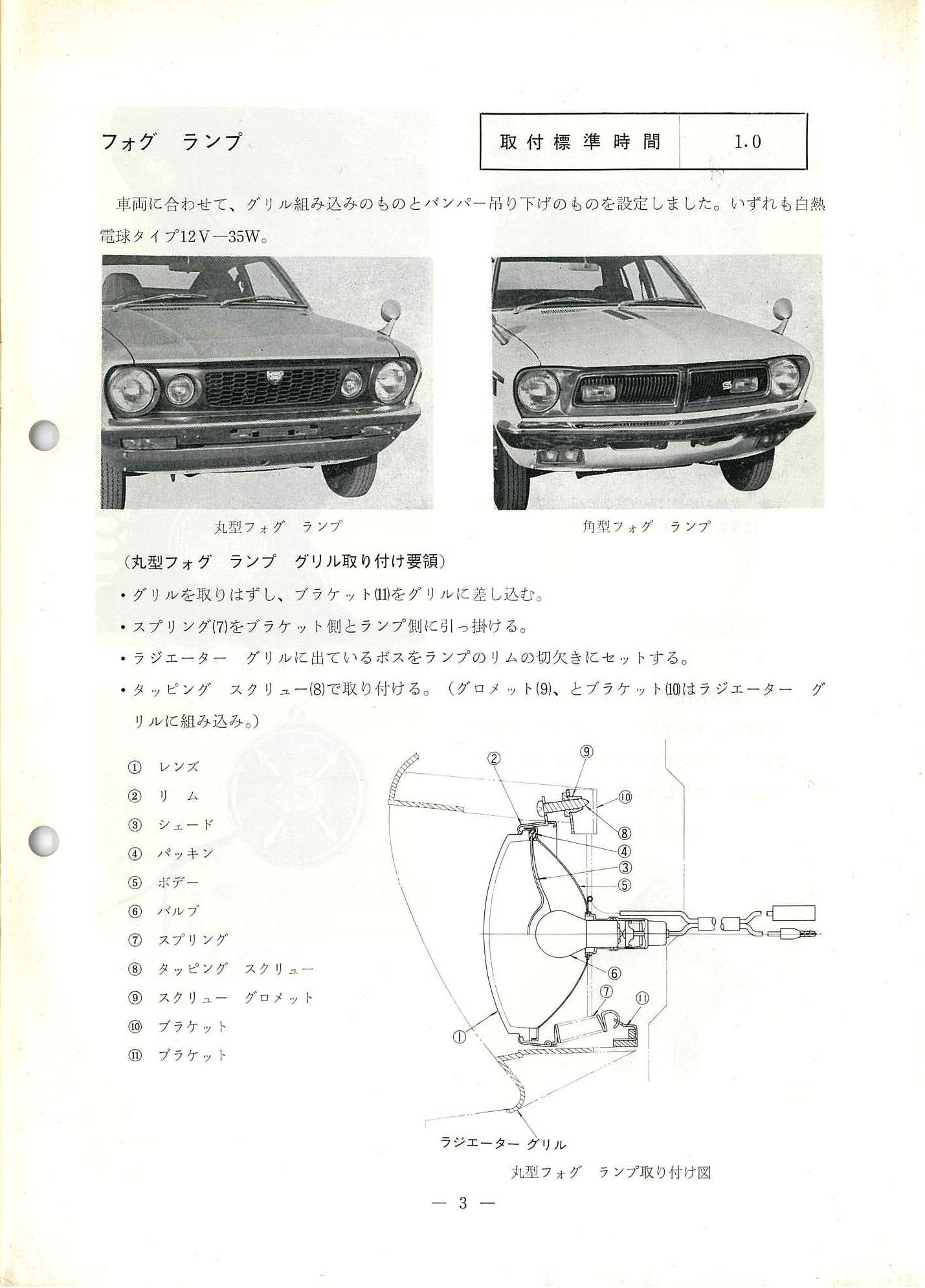
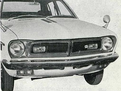
車両に合わせて、グリル組み込みのものとバンパー吊り下げのものを設定しました。いずれも白熱電球タイプ 12V-35W
Depending on the vehicle, we have set one with a built-in grille and one that hangs from the bumper. All incandescent bulb types 12V-35W
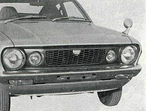
丸型フォグ ランプ
Round-type Fog Lamps
角型フォグ ランプ
Rectangular-type Fog Lamps
Round-type Installation Instructions
(丸型フォグ ランプ グリル取り付け要領)
(Round fog lamp grill installation instructions)
* グリルを取りはずし、ブラケットをグリルに差し込む。
* Remove the grill and insert the bracket into the grill.
* スプリング(7)をブラケット側とランプ側に引っ掛ける。
* Hook the spring (7) onto the bracket side and lamp side.
* ラジエーター グリルに出ているボスをランプのリムの切欠きにセットする。
* Set the boss on the radiator grille into the notch in the lamp rim.
* タッピング スクリュー(8)で取り付ける。(グロメット(9)、とブラケット(10)はラジエーターグリルに組み込み。)
* Attach with self-tapping screw (8). (The grommet (9) and bracket (10) are assembled into the radiator grill.)
1. レンズ
2. リ ム
3. シェード
4. パッキン
5. ボヂー
6. バルブ
7. スプリング
8. タッピング スクリュー
9. スクリュー グロメット
10. ブラケット
11. ブラケット
1. Lens
2. Rim
3. Shade
4. Packing
5. Body
6. Bulb
7. Spring
8. Tapping screw
9. Screw grommet
10. Bracket
11. Bracket
(A) ラジエーターグリルを指します
(A) points to Radiator Grille

丸型フォグ ランプ取り付け図
Round fog lamp installation diagram
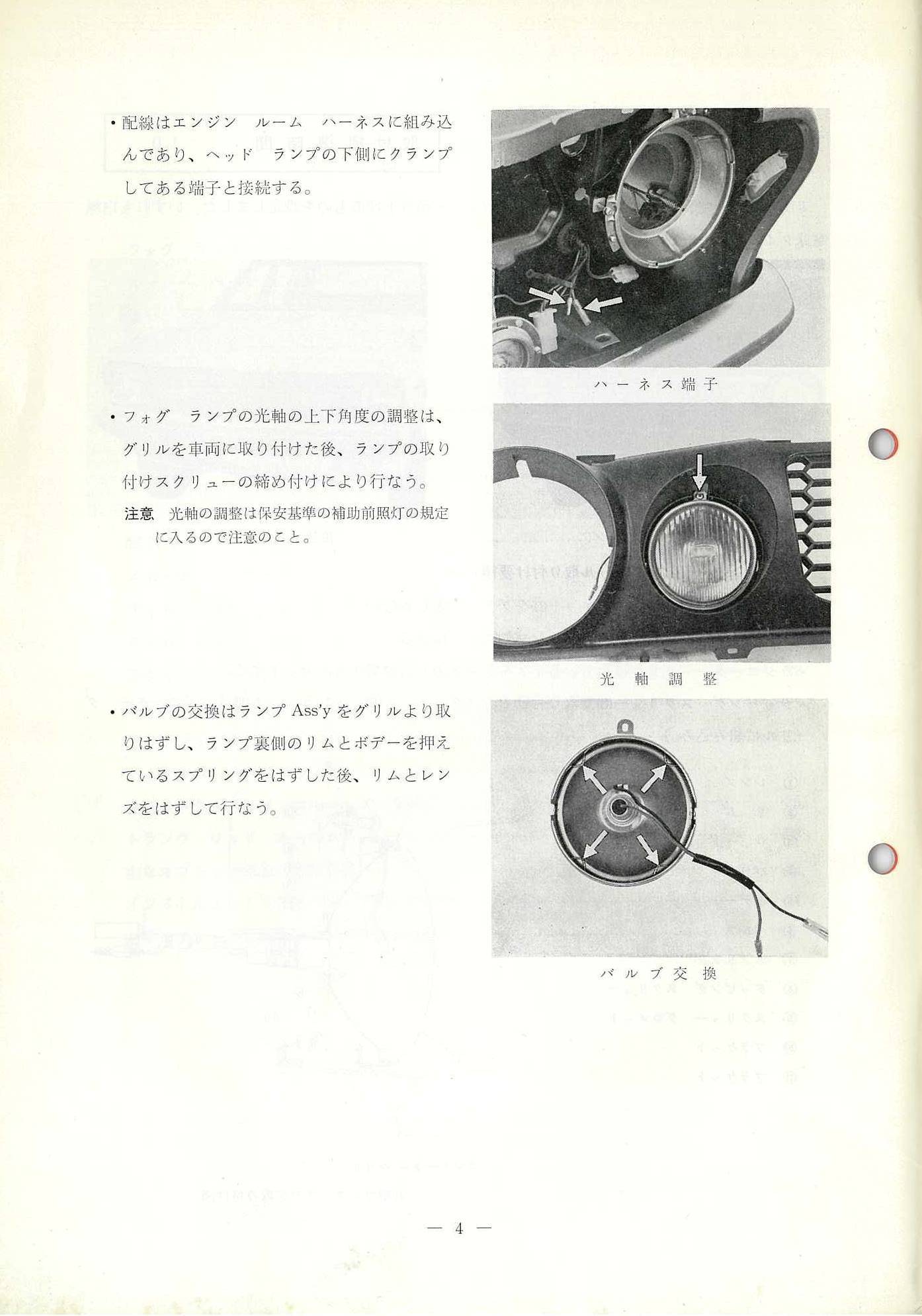
・配線はエンジンルーム ハーネスに組み込 んであり、ヘッドランプの下にクランプ してある端子と接続する。
* The wiring is built into the harness in the engine room and connected to the terminal clamped under the headlamp.
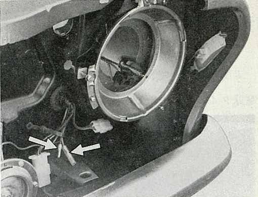
ハーネス端子
Harness terminal
・フォグランプの光軸の上下角度の調姿は、 グリルを車両に取り付けた後、ランプの取り 付けスクリューの締め付けにより行なう。
注意、光軸の調整は保安基準の補助前照灯の規定 に入るので注意のこと。
* Adjust the vertical angle of the fog lamp optical axis by tightening the lamp installation screws after installing the grille on the vehicle.
NOTE: Please note that the adjustment of the optical axis falls under the regulations for auxiliary headlamps in the safety standards.
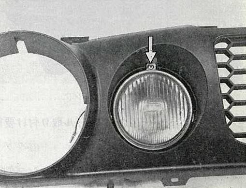
光軸調整
Optical axis adjustment [Aiming Screw]
・バルブの交換はランプをグリルより取 りはずし、ランプ裏側のリムとボデーを押え ているスプリングをはずした後、リムとレン ズをはずして行なう。
* To replace the bulb, remove the lamp assembly from the grille, remove the spring holding the rim and body on the back of the lamp, and then remove the rim and lens.
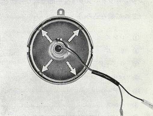
バルブ交換
Bulb replacement [screws]
Rectangular-type Installation Instructions
[These lamps are used by PB210 Sunny Excellent]
(角型フォグランプ グリル取り付け要領)
(Square fog lamp grill installation instructions)
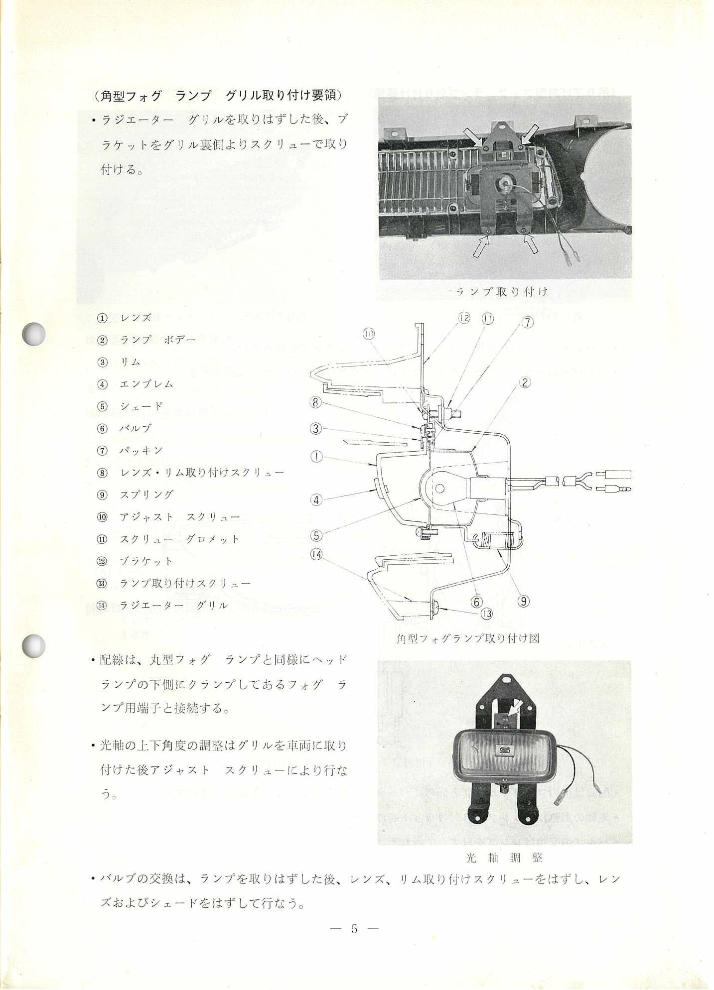
・ラジエーター グリルを取りはずした後、ブラケットをグリル裏側よりスクリューで取り 付ける。
* After removing the radiator grill, install the bracket from the back of the grill with screws.
ランプ取り付け
Lamp Installation
角型ファグランプ取り付け図
Square Fog Lamp Installation Diagram
① レンズ
② ランプ ボデー
③ リム
④ エンブレム
⑤ シェード
⑥ バルブ
⑦ パッキン
⑧ レンズ・リム取り付けスクリュー
⑨ スプリング
⑩ アジャスト スクリュー
⑪ スクリュー グロメット
⑫ ブラケット
⑬ ランプ取り付けスクリュー
⑭ ラジエーター グリル
① Lens
② Lamp body
③ Rim
④ Emblem
⑤ Shade
⑥ Valve
⑦ Packing
⑧ Lens/rim mounting screw
⑨ Spring
⑩ Adjustment screw
⑪ Screw grommet
⑫ Bracket
⑬ Lamp installation screw
⑭ Radiator grill
・配線は、丸型フォグランプと同様にヘッド ランプの下側にクランプしてあるフォグラ ンプ用端子と接続する。
* Connect the wiring to the fog lamp terminal that is clamped to the bottom of the headlamp in the same way as for round fog lamps.
・光軸の上下角度の調整はグリルを車両に取り 付けた後アジャスト スクリューにより行なう。
* Adjust the vertical angle of the optical axis using the adjustment screw after installing the grille on the vehicle.
・バルブの交換は、ランプを取りはずした後、レンズ、リム取り付けスクリューをはずし、レン ズおよびシェードをはずして行なう。
* To replace the bulb, remove the lamp, then remove the lens and rim mounting screws, and then remove the lens and shade.
光軸調整
Optical axis adjustment [Aiming Screw]
— 5 —
Bumper Hanging-type Installation Instructions
(吊り下げ角型フォグランプ取り付け要領)
(Hanging Square Fog Lamp Installation Instructions)
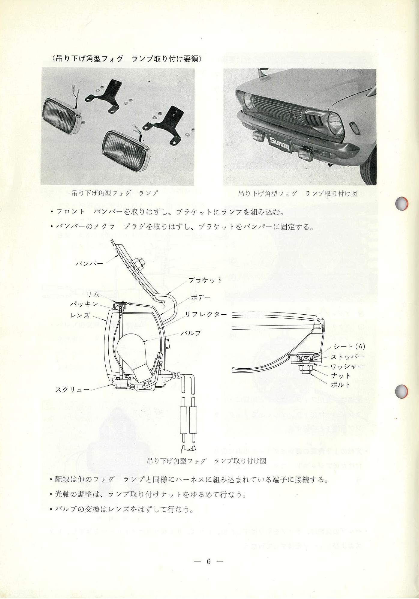
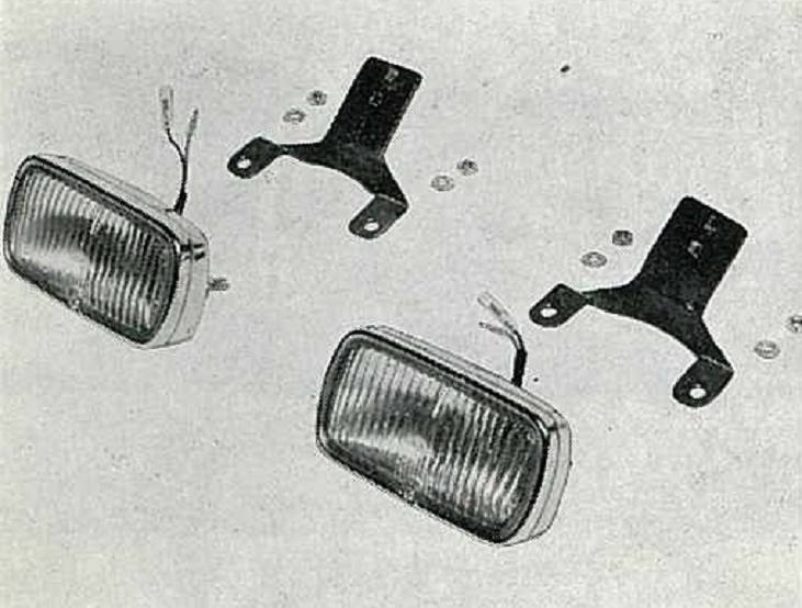
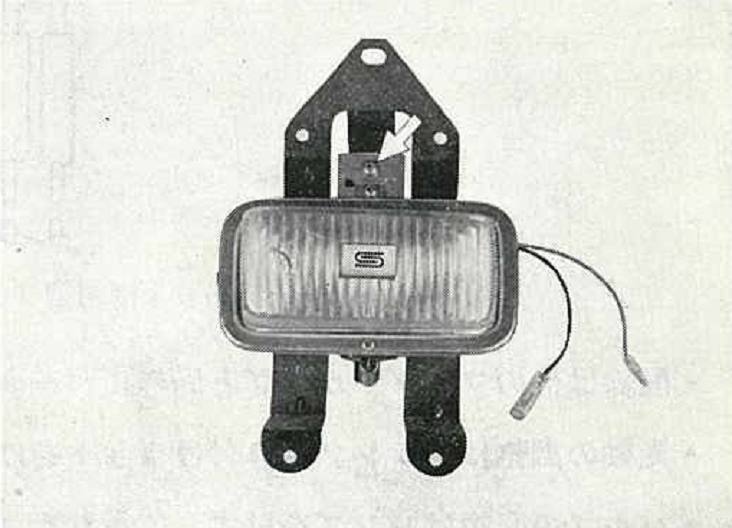
吊り下げ角型フォグランプ
Hanging Square Fog Lamp
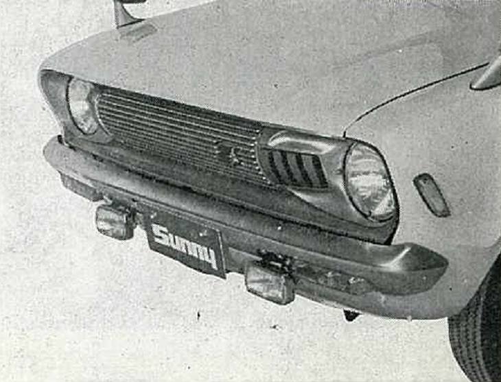
吊り下げ角型フォグランプ取り付ける
Installing a hanging square fog lamp
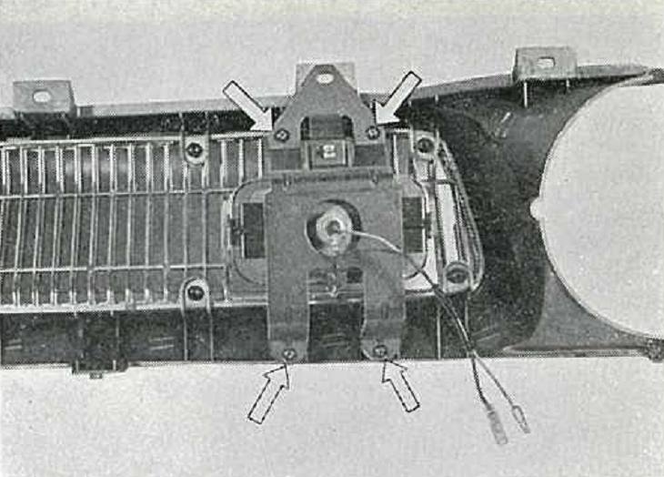
・フロントバンパーを取りはずし、ブラケットにランプを組み込む。
* Remove the front bumper and install the lamp into the bracket.
・バンパーのメクラ プラグを取りはずし、ブラケットをバンパーに固定する。
* Remove the blind plug from the bumper and fix the bracket to the bumper.
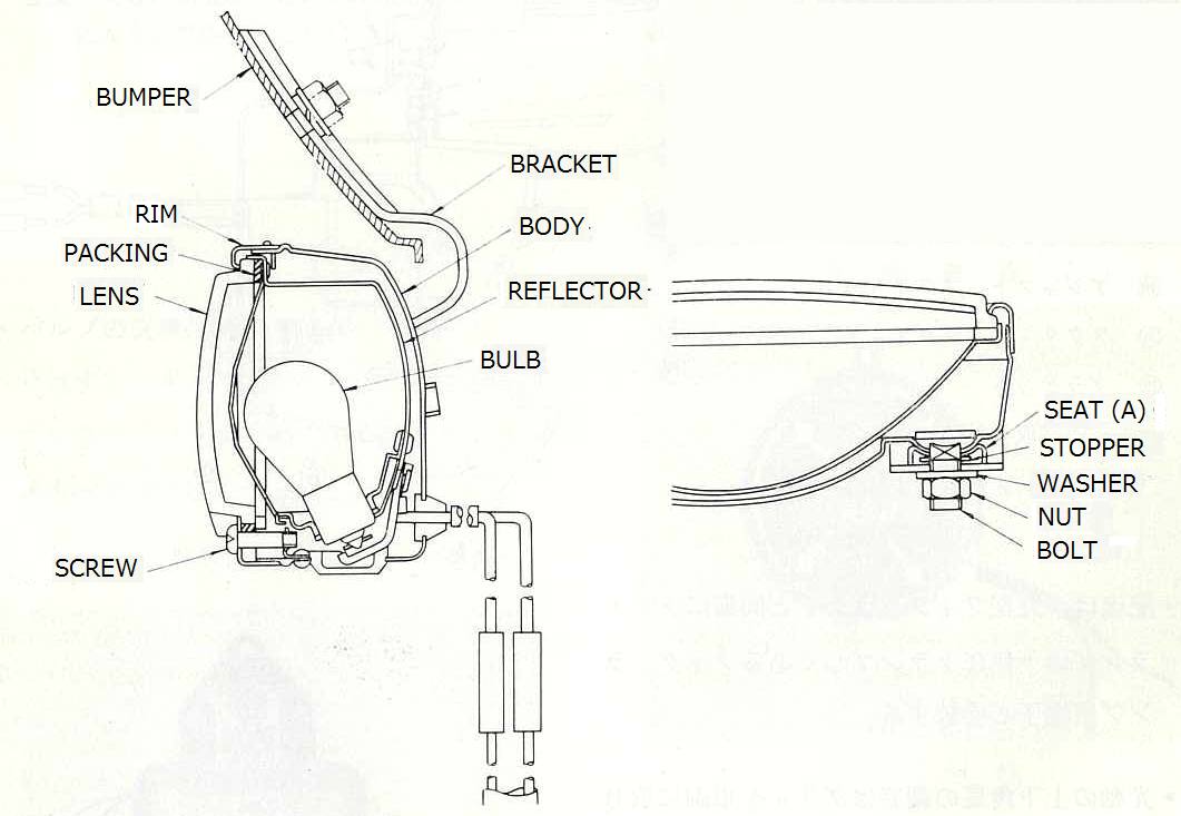
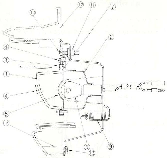
吊り下げ角型フォグランプ取り付け図
Hanging Square Fog Lamp Installation Diagram
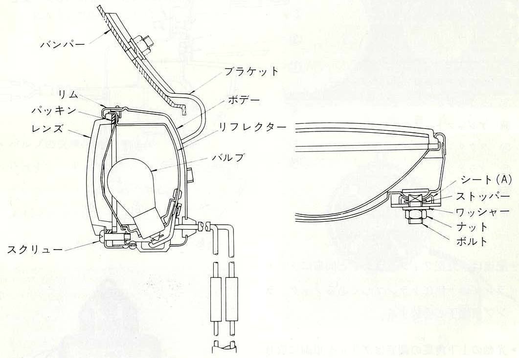
・配線は他のフォグランプと同様にハーネスに組み込まれている端子に接続する。
* Connect the wiring to the terminal built into the harness like other fog lights.
・光軸の調整は、ランプ取り付けナットをゆるめて行なう。
* To adjust the optical axis, loosen the lamp mounting nut.
・バルブの交換はレンズをはずして行なう。
* Remove the lens before replacing the bulb.
— 6 —
Overhead Console
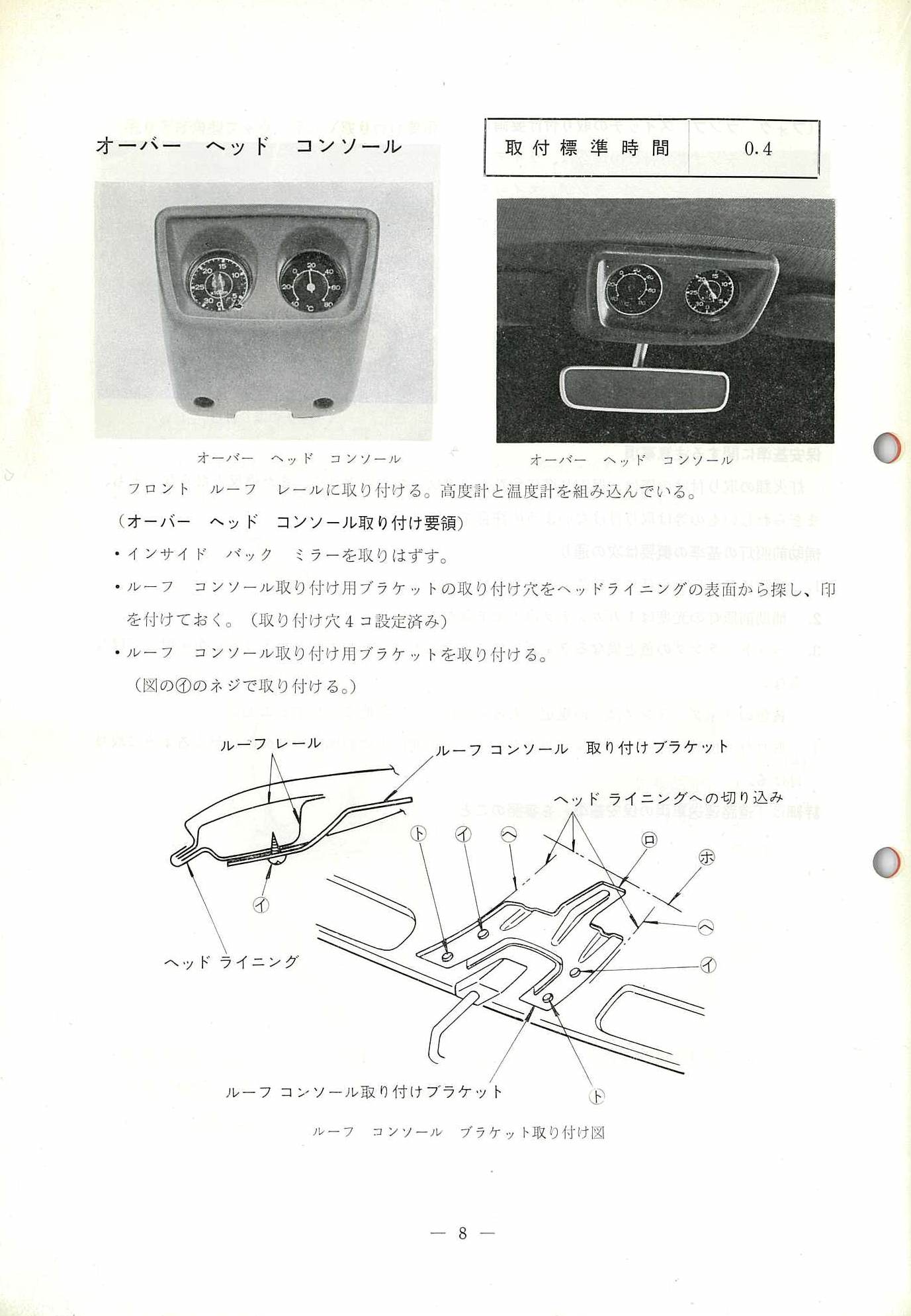

オーバー ヘッド コンソール
Overhead Console
取付標準時間 0.4
Installation standard time 0.4
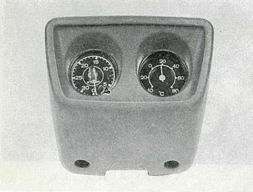
オーバー ヘッド コンソール
overhead console

オーバー ヘッド コンソール
overhead console
Photo from brochure:
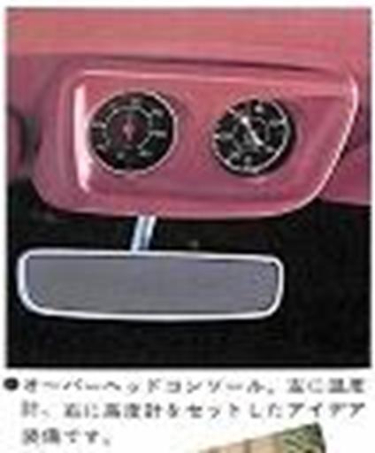
フロント ルーフ レールに取り付ける。高度計と温度計を組み込んでいる。
(オーバー ヘッド コンソール取り付け要頠)
Attach to the front roof rail. It has a built-in altimeter and thermometer. (Overhead console installation required)
・インサイド バック ミラーを取りはずす。
* Remove the inside rearview mirror.
・ルーフ コンソール取り付け用ブラケットの付け穴をフヘッドライニングの表面から探し、印を付けておく。(取り付け穴コ4設定済み)
* Locate and mark the mounting holes for the roof console mounting bracket on the surface of the roof lining. (4 mounting holes already set)
・ルーフ コンソール取り付け用ブラケットヲ取り付けす。
(図の(イ)のネジで取り付ける。)
* Install the roof console mounting bracket.
(Attach with the screws shown in (A) in the figure.
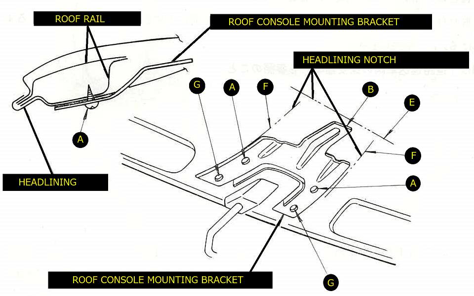
ルーフ コンソール ブラケット取り付け図
Roof console bracket installation diagram
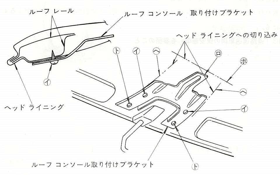
・ルーフ コンソールの爪部分(ハ)をブラケットの爪(ロ)に引っかけて仮り止めし、ヘッドライニングにコンソールの(ニ)の長さを印しておく。
(下図の(ニ)の部分にチョーク等を塗っておき(ニ)の長さがヘッドライニングの表面に印が付くよう
にすれと?い。)
* Hook the claw part (C) of the roof console onto the nail (B) of the bracket to temporarily secure it, and mark the length of the console (D) on the headlining.
(Apply chalk, etc. to the part (D) in the diagram below, and make sure to mark the length (D) on the surface of the headlining.)
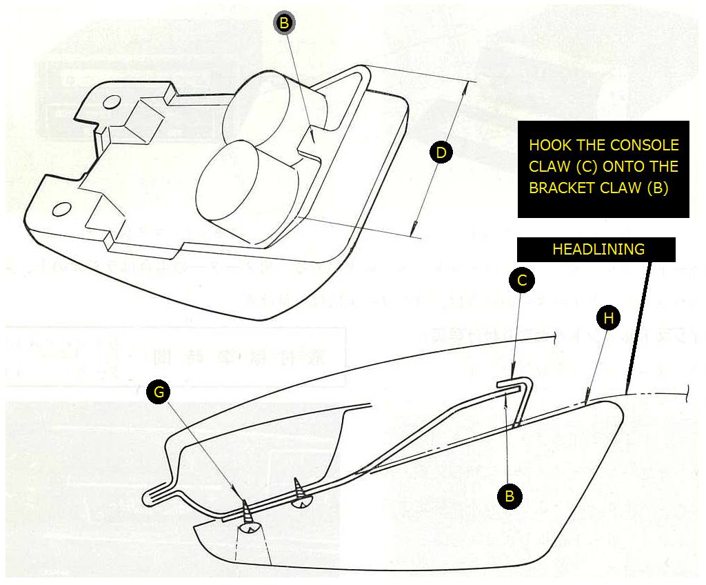
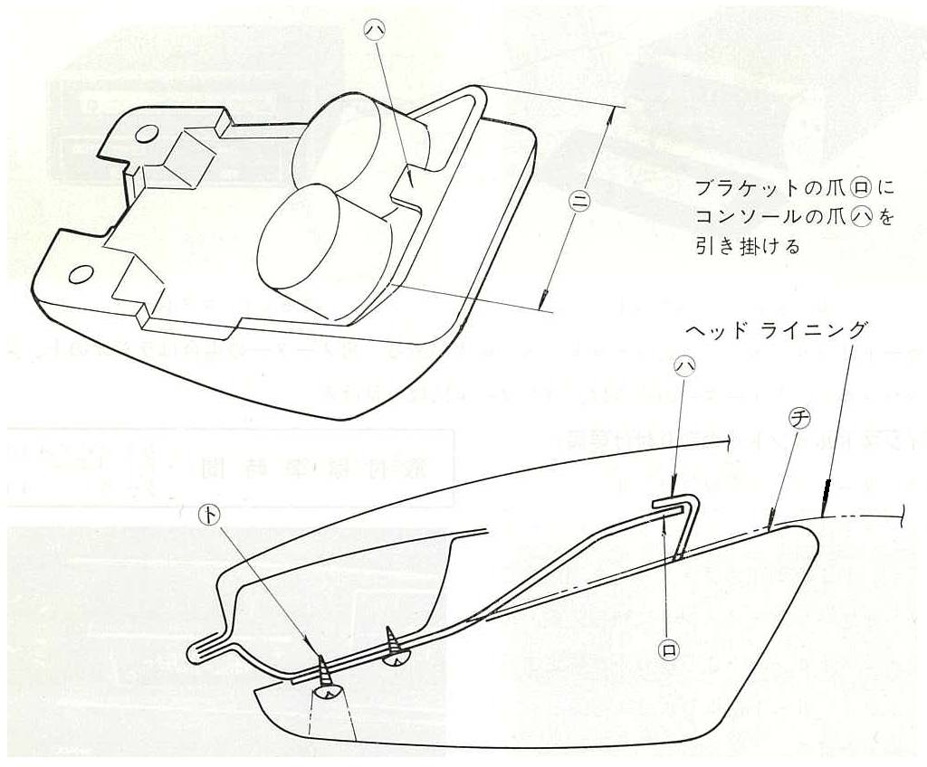
コンソール取り付け要頜図
Console installation diagram
・仮り止めしたルーフ コンソールをはずし、ヘッドライニングに印した(ニ)の長さでけナイフ等で切る。(前頁ブラケット取り付け図(ホ)参照)
* Remove the temporarily attached roof console and cut the length marked (d) on the headlining with a knife, etc. (Refer to the bracket installation diagram (E) on the previous page)
ブラケットの左右の端にも同様にナイフを人れて切る。(ブラケット取り付け図(ヘ)参照)注意 前記ヘッドライニングの切り込み((ホ)、(ヘ))長さは長くならいよらにすること。長くすれとルーフコノソール取り付け後、切り込みが見えてしまうので注意のこと。
* Cut the left and right ends of the bracket with the knife in the same way. (Refer to the bracket installation diagram (F)) Caution: The length of the notches ((E), (F)) in the headlining should not be too long. Be careful as the notch will be visible after the roof console is installed.
・コンソールの爪をブラケットに引っ掛け、コンソールとブラケットをスクリューで共締めする。
* Hook the console claw onto the bracket, and tighten the console and bracket together with the screws.
・ヘッドライニングに切り込み入れた(ホ)、(ヘ)をルーフコンソールの(チ)の線まで下げる。(コンソール仮リ止め要領図参照)
* Lower the (E) and (F) cuts into the headlining to the (C) line on the roof console. (Refer to the procedure for temporarily fixing the console)
・インサイド バック ミラーを取り付ける。
* Install the inside rearview mirror.
Car Stereo
NOTE: if you'd like this section of the catalog translated, reply to POST this post
Page 10
カー ステレオ
Car Stereo
Clock
NOTE: if you'd like this section of the catalog translated, reply to POST this post
Page 12
時 計
Clock
Radio (AM-FM)
NOTE: if you'd like this section of the catalog translated, reply to POST this post
Page 15
ラヂオ(AM-FM)
Radio (AM-FM)
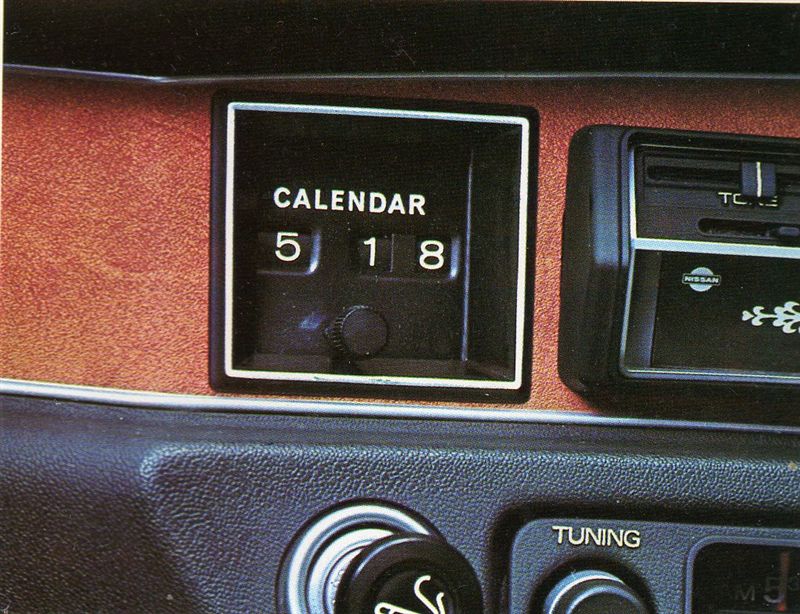
Calendar
NOTE: if you'd like this section of the catalog translated, reply to POST this post
Page 16
カレンダー
Calendar
25511-H5100
Ammeter
NOTE: if you'd like this section of the catalog translated, reply to POST this post
Page 17
電流計
Ammeter
Oil Pressure Gauge
NOTE: if you'd like this section of the catalog translated, reply to POST this post
Page 18
油圧計
Oil Pressure Gauge
Voltmeter
NOTE: if you'd like this section of the catalog translated, reply to POST this post
Page 19
電圧計
Voltmeter
Intermittent Wipers
NOTE: if you'd like this section of the catalog translated, reply to POST this post
Page 20
間歇ワイパー
Intermittent Wipers
Sport Visor
NOTE: if you'd like this section of the catalog translated, reply to POST this post
Page 21
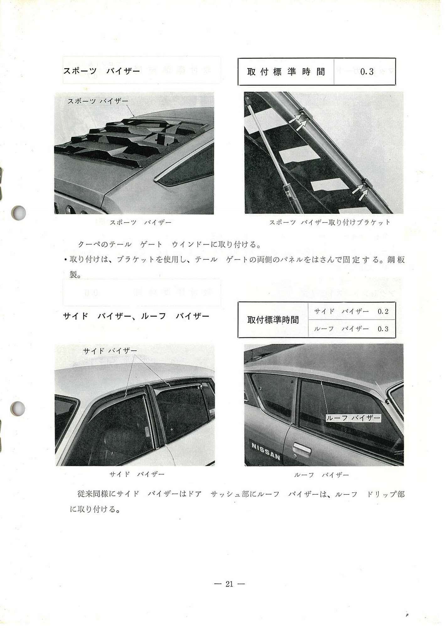
スポーツ バイザー
Sport Visor
Side Visor, Roof Visor
サイド バイザー、ルーフ バイザー
Side Visor, Roof Visor
editors NOTE:
* sport visor = rear window louver
* side visor = Sedan rain visor
* roof visor = Coupe rain visor (one-piece)
スポーツ バイザー
Sport Visor
取付標準時間 0.3
Installation standard time 0.3
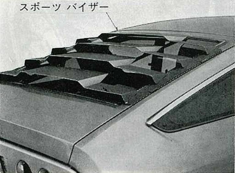
スポーツ バイザー
Sport Visor
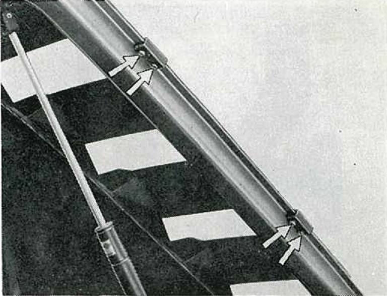
スポーツ バイザー取り付け付ブラケット
Sport visor mounting bracket
クーペのテール ゲート ウインドーに取り付けい。
Attach to the coupe's tailgate window.
・耳り付けは、ブラケットを使用し、テール ゲートの雨側のパネルをはさんで固定する。鋼板製。
*To attach the ears, use a bracket and secure it by sandwiching the rain side panel of the tailgate. Made of steel plate.
サイド バイザー、ルーフ バイザー
Side Visor, Roof Visor
取付標準時間
サイド バイザー 0.2
ルーフ バイザー 0.3
Installation standard time 0.2
Installation standard time 0.3
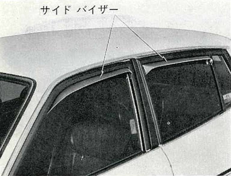
サイド バイザー
Side Visor
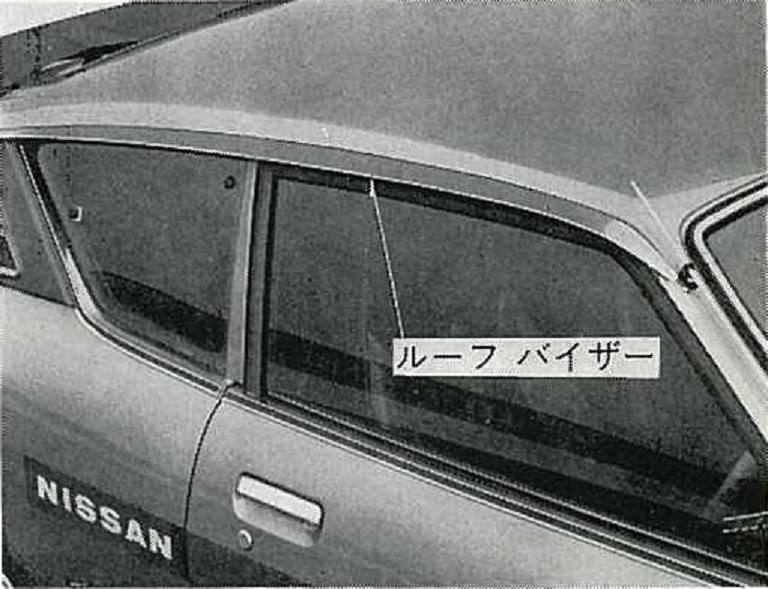
ルーフ バイザー
Roof Visor
従来同様にサイド バイザーはドア サッシュ部にルーフ バイザーは、ルーフ ドリップ部に取り付けす。
As before, the side visors are attached to the door sash area, and the roof visors are attached to the roof drip area.
Mudguards
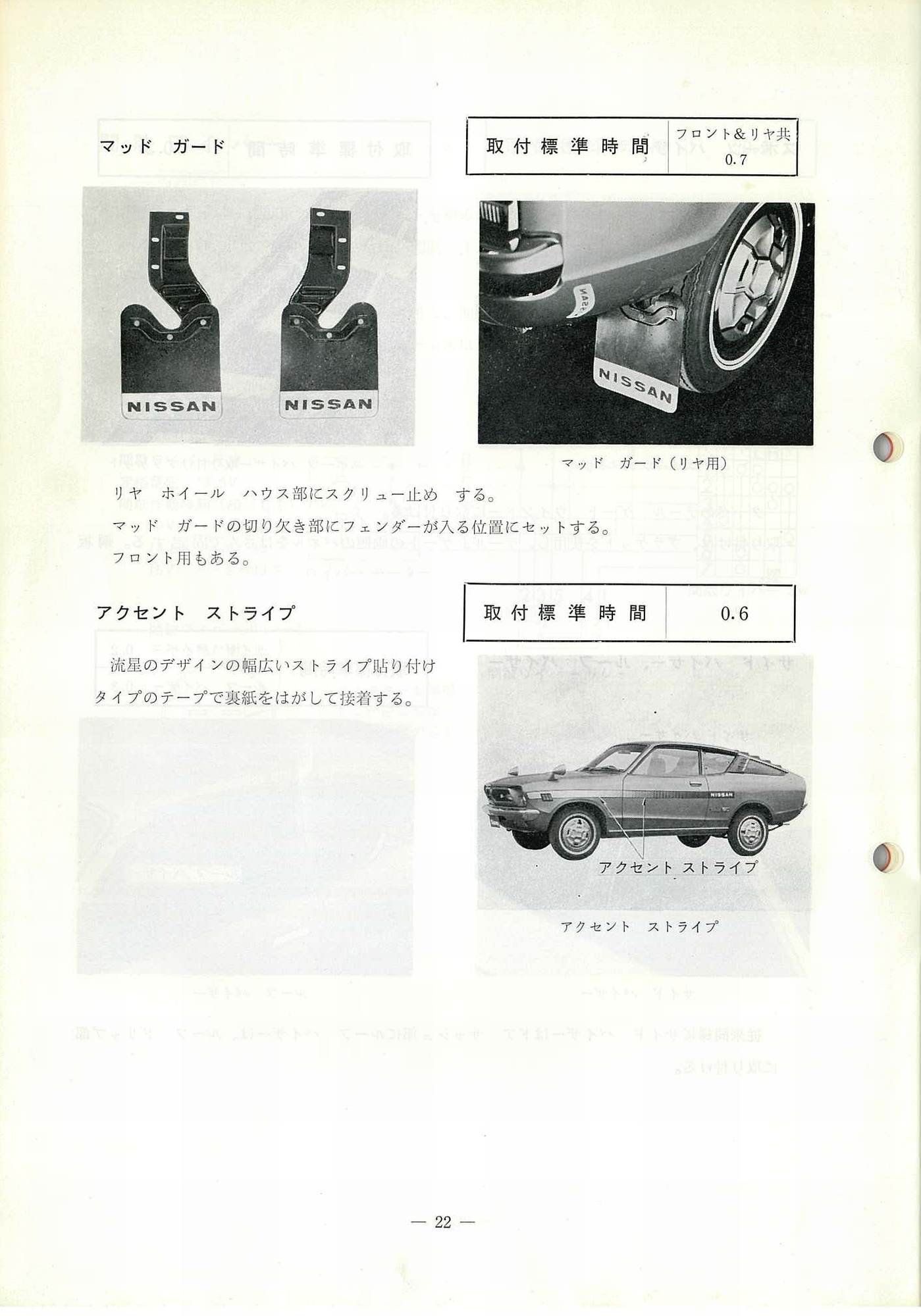
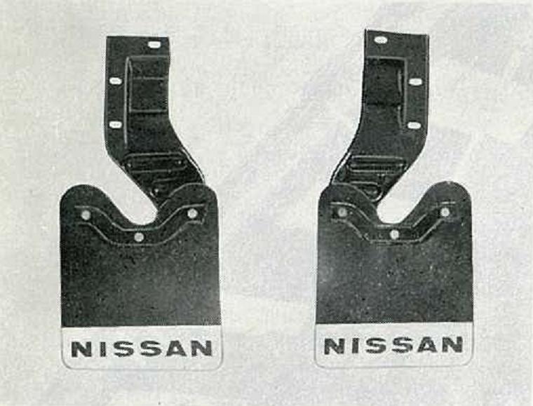
マッド ガード
Mudguards
取付標準時間 フロント&リヤ共 0.7
Installation standard time front & rear both 0.7
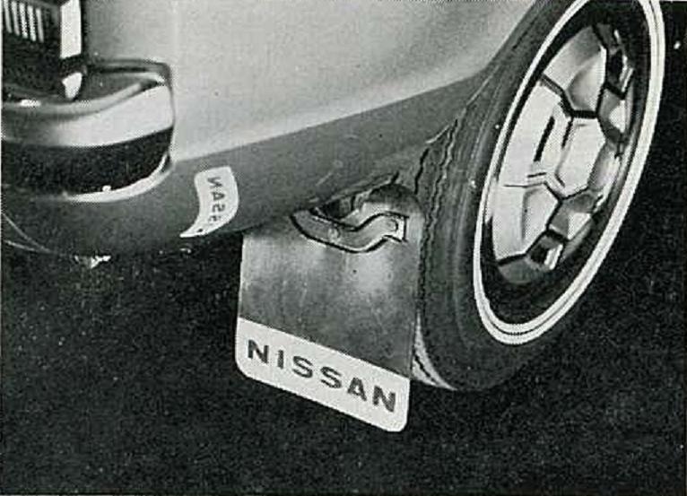
マッド ガード (リヤ用)
Mudguard (rear)
リヤ ホイール ハウス部にスクリュー止め する。
マッド ガードの切切り欠き部にフィンダーが入る位置にセットする。
フロント用もある。
Screw down til stop on the rear wheel house.
Set the position where the fender goes into the notch of the mud guard.
There is also mudguards for the front.
Accent Stripe
アクセント ストライプ
Accent Stripe
取付標準時間 0.6
Installation standard time 0.6
流星のデザインの幅広いストライプ貼り付けタイプのテープで裏紙紐をはがして接着する。
Peel and bond the backing strip with a wide stripe-paste-type tape of meteor design.
PB210 pictured
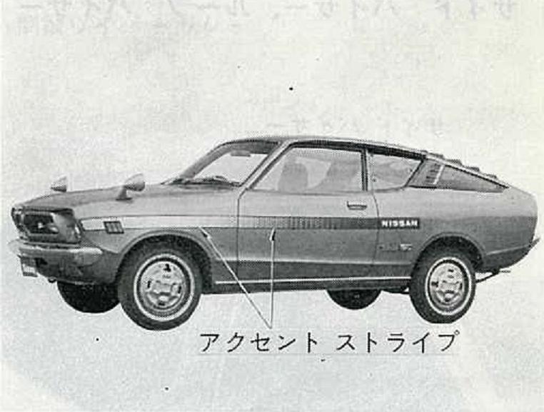
アクセント ストライプ
Accent Stripe
Wood Grain Steering Wheel
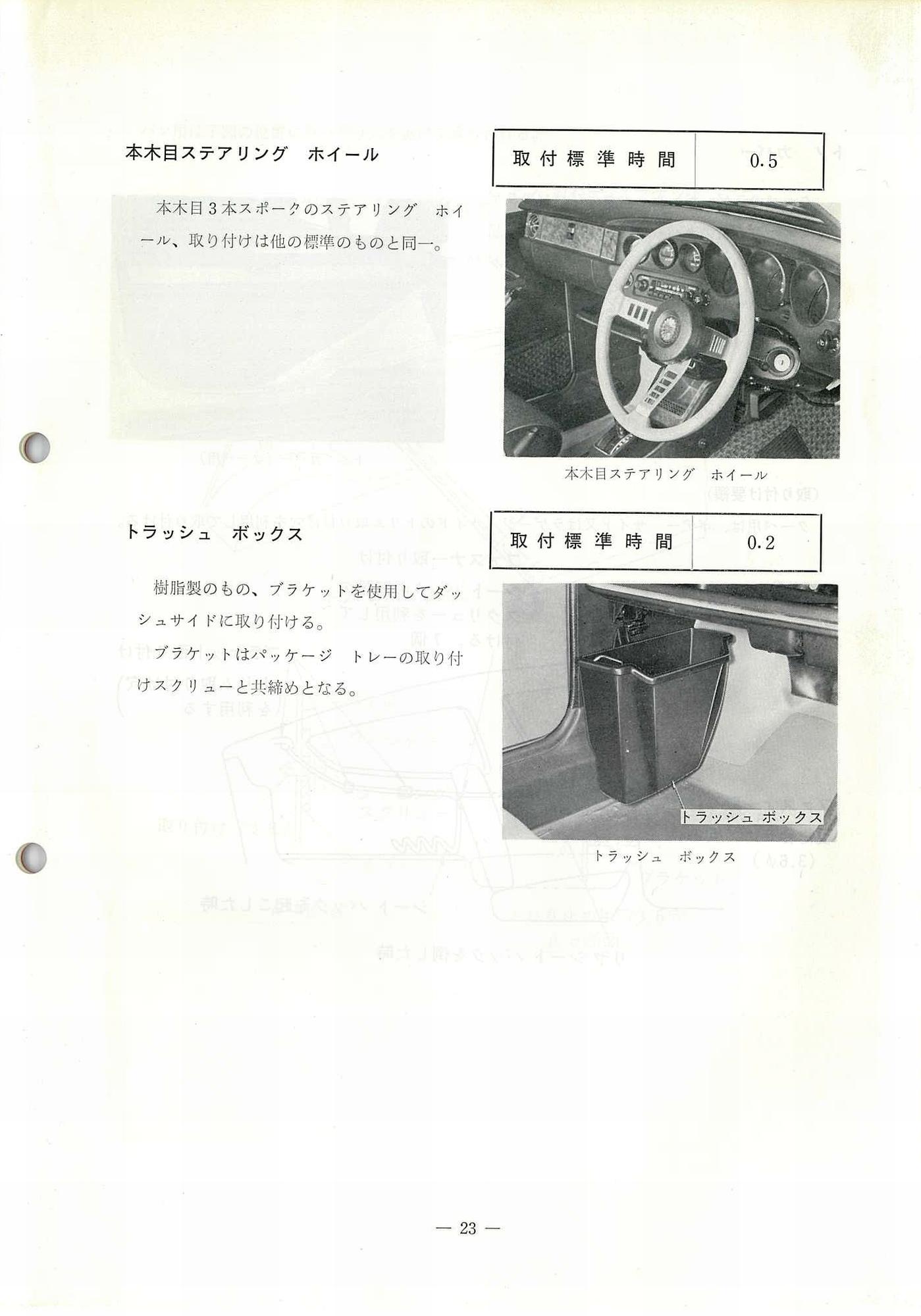
本木目ステアリング ホイール
Wood Grain Steering Wheel
取付標準時間 0.5
Installation standard time 0.5
本木目3本スポークのステアリング ホイール、取り付けは他の標準のものと同-。
3-spoke wood grain steering wheel, mounting same as other standard ones.
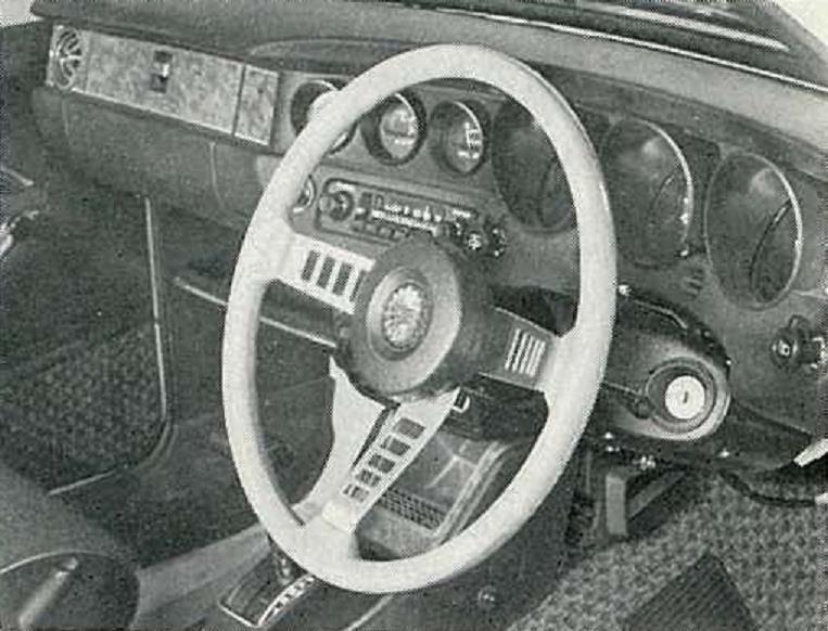
本木目ステアリング ホイール
Wood Grain Steering Wheel
Trash Box
トラッシュ ボックス
Trash Box
取付標準時間 0.2
Installation standard time 0.2
樹脂製のもの、ブラケットを使用してダッシュサイドに取り付ける。
ブラケットはパッケージ トレーの取り付けスカリューと共締めとなる。
Attached to the dash side using resin and brackets.
The bracket is co-fastened with the package tray mounting screw.
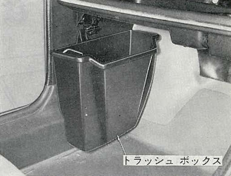
トラッシュ ボックス
Trash Box
F7880-H5000ᴳ
Tonneau Cover
NOTE: if you'd like this section of the catalog translated, reply to POST this post
Page 24
トノカバー
Tonneau Cover
Tachometer (and Tach-Volt Meter)
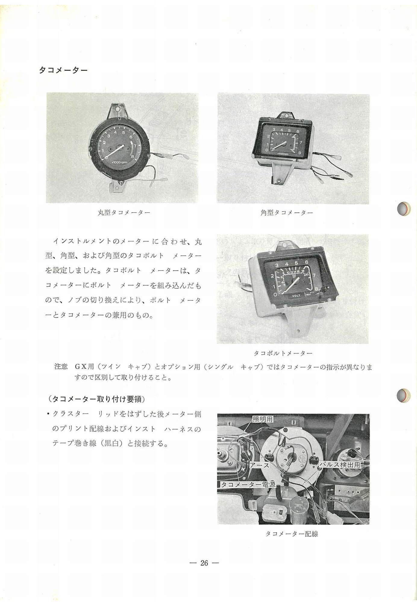
タコメーター
Tachometer
丸型タコメーター
Round type Tachometer
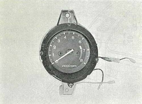
角型タコメーター
Angle type Tachometer

タコボルトメータ
Tach-Volt Meter
インストルメントのメーターに合わせ、丸型、角型、および角型のタコボルト メーターを設定しました。タコボルト メーターは、タコメーターにボルト メーターを組み込んだもので、ノブの切りま換えにより、ボルト メーター ーとタコメーターの兼用のもの。
Round, square, and square tach-volt meters are set to match the instrument's meter. The tach-voltmeter is a tachometer with a volt meter built-in. By switching the knob, the tachometer is used both as a volt meter and a tachometer.
注意GX用(ツイン キャブ)とオプション用(シングル キャブ)ではタコメーターの指示が異なりますので区別して取り付けること。
NOTE: The instructions for the tachometer differ between the GX use (twin cab) and the option use (single carb).
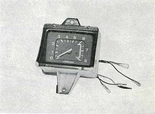
(タコメーター取付け要領)
・クラスター リッドをはずした後メーター側のプリント配線およびインスト ハーネスのテープ巻き線(黒白)と接続する。
(How to install the tachometer)
* After removing the cluster lid, connect the tachometer wires to the printed-wiring connectors on the meter side, and with the tape winding (black and white wires) of the instrument harness.
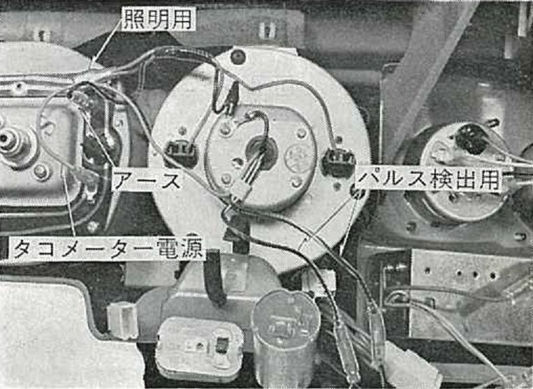

タコメーター配線
Tachometer Wiring
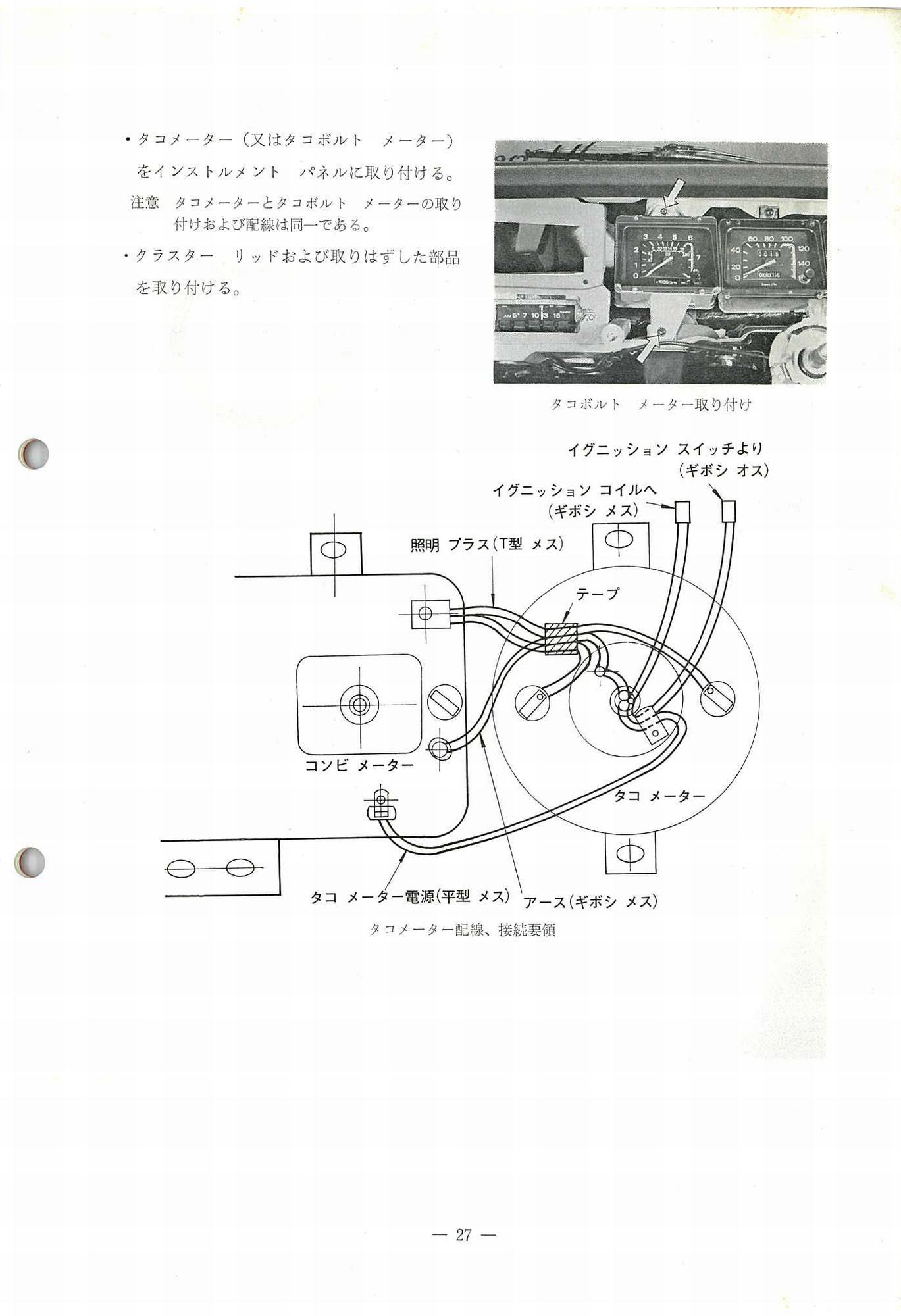
・ タコメーター (又はタコボルト メーター)をインストルメント パネルに取り付ける。
注意 タコメーターとタコボルト メーターの取り付けおよび配線は同-である。
・ クラスター リッドおよび取りはずした部品を取り付ける。
Attach tachometer (or tach-volt meter) to the instrument panel.
NOTE: The installation and wiring of the tachometer and tach-volt meter are the same.
Install the cluster lid and removed parts.
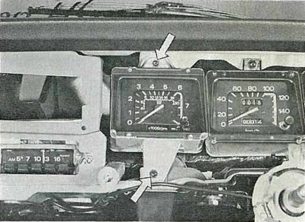
タコボルト メーター取り付け
Tacho-Volt Meter Attachment
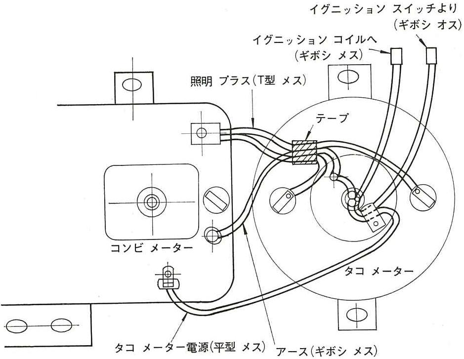
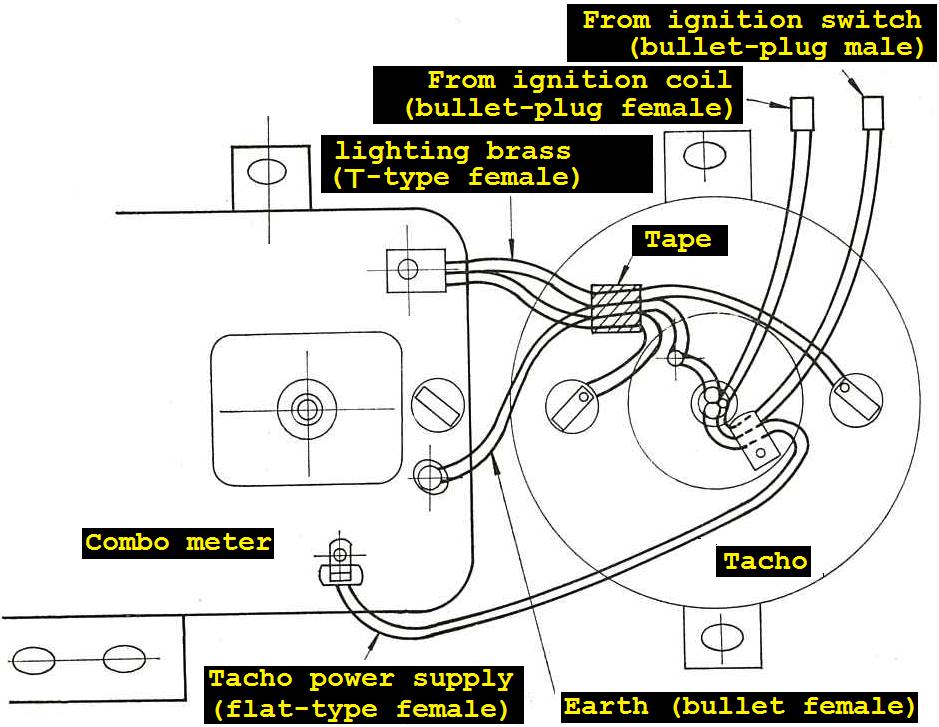
タコメーター配線、接続要領
Tachometer wiring, connection points
| イグニッション スイッチより (ギボシ オス) | From ignition switch (bullet-plug male) |
| イグニッション コイルヘ (ギボシ メス) | From ignition coil (bullet-plug female) |
| 照明 ブラス(丅型 メス) | lighting brass (vertical-type female) |
| テープ | Tape |
| コンビ メーター | Combination meter |
| タコ メーター | Tachometer |
| タコ メーター電源(平型 メス) | Tachometer power supply (flat-type female) |
| アース(ギボシ メス) | Earth (bullet-plug female) |
Trunk Lid Opener
NOTE: if you'd like this section of the catalog translated, reply to POST this post
Page 28
トランク リッド オープナー
Trunk Lid Opener
Wiring Procedure of the Main Options Parts}
NOTE: if you'd like this section of the catalog translated, reply to POST this post
Page 33
主なオプション部品の配線要領
Wiring Procedure of the Main Options Parts
Instrument Lower Unit Mounting Drawing
NOTE: if you'd like this section of the catalog translated, reply to POST this post
Page 33
インストルメント下側ユニット取り付け図
Instrument Lower Unit Mounting Drawing
Main Optional Parts Installation Standard Working Time
NOTE: if you'd like this section of the catalog translated, reply to POST this post
巻末
End
Page 35
主要オプション部品取り付け標準作業時間
Main optional parts installation standard working time
Publisher's Page
不許複製
All rights reserved
印刷発行 昭和48年5月
Printed and published May 1973
行所 日産自動車株式会社
Location: Nissan Motor Co., Ltd.
サービス 部
東京都中央区銀座6一17一1
Service Department
6-17-1 Ginza, Chuo-ku, Tokyo
T一305045
T-305045