![[Datsun 1200 encyclopedia]](/wiki/upload/wiki.png)
| Revision as of 03:56, 6 October 2016 ddgonzal (Talk | contribs) (->Automatic Choke) <- Previous diff |
Revision as of 04:04, 6 October 2016 ddgonzal (Talk | contribs) (->Automatic Choke) Next diff -> |
||
| Line 81: | Line 81: | ||
| = Automatic Choke = | = Automatic Choke = | ||
| NOTE: If your Datsun was factory-equipped with [[Automatic Choke]], jumper is needed at the choke relay connector. The wiring above (two jumpers) will work correctly for charging, but does not fix the choke relay. | NOTE: If your Datsun was factory-equipped with [[Automatic Choke]], jumper is needed at the choke relay connector. The wiring above (two jumpers) will work correctly for charging, but does not fix the choke relay. | ||
| + | |||
| + | METHOD 1: Unplug the Relay, then in the relay connector in the harness, Jump Blue wire to Red wire. This bypasses the relay. | ||
| + | |||
| + | METHOD 2: Retain operation of relay. Cut the Yellow wire at the Relay and run a new wire to the Lamp wire in the harnes. You can unwrap the harness and make the modification neatly inside OR connect it to the long two-wire T-connector harness. | ||
| + | |||
| + | METHOD 3: Obtain new-style relay and rewire engine compartment. | ||
| == Original Wiring Comparo == | == Original Wiring Comparo == | ||
Revision as of 04:04, 6 October 2016
The Hitachi LR Alternator series uses the same T-connector but wiring is different. If you use this newer type in an early Datsun 1200 the external voltage regulator must be disconnected a minor wiring changes made.
Contents |
Overview
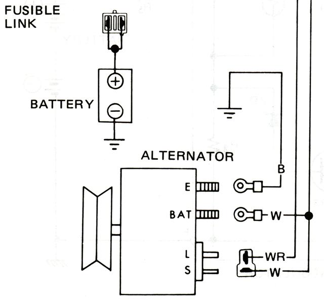
JAPAN Datsun 1200 starting in 1981 uses an internally-regulated Hitachi LR-135 alternator. North America Datsun starting 1978 also used 35A, 50A or 60A versions. All are wired the same way.
L - Lamp (stem of T) -> To dash 'CHG' Lamp
S - Sense (head of T) -> to BAT+ via Fusible Link
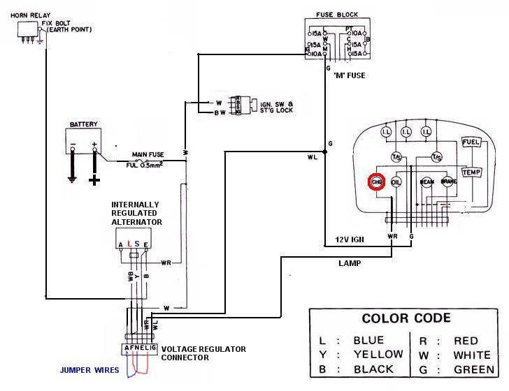
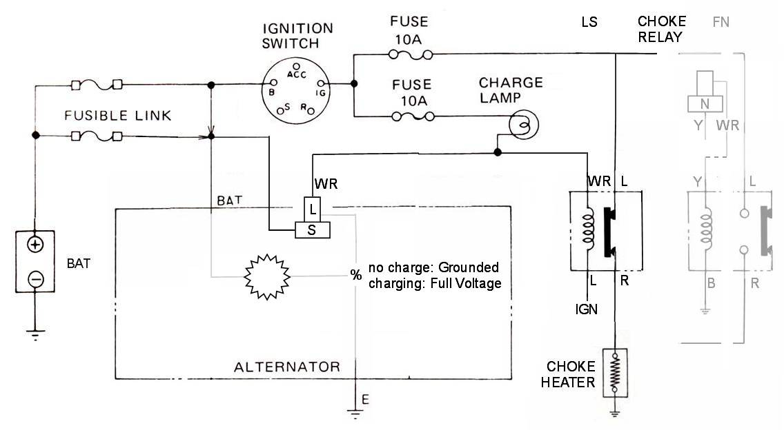
Here is the factory wiring diagram portion:
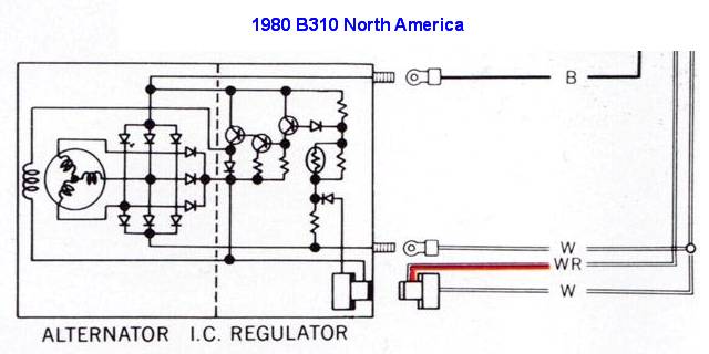
Notice the I.C Alternator T-connector head is connected to BAT+ line(unswitched battery voltage). 1978 B210 is the same but wire colors differ.
1979-1982 B310 North America colors
B - Black wire. Earth/Ground
W - thick White wire. BAT+ via Fusible Link
W - thin White wire in T-connector head. BAT+ via Fusible Link
WR - White/Red in T-connector stem. To dash 'CHG' Lamp
Notice that the I.C Alternator T-connector head is connected to A/BAT terminal (unswitched battery voltage). The splice occurs in the wiring harness.
1978 B210 Colors
B - Black wire. Earth/Ground
WR - White/Red. BAT+ via Fusible Link
Y - Yellow. T-connector head. BAT+
WB - White/Red. T-connector stem. To dash 'CHARGE' Lamp
Fitting To Early Datsuns
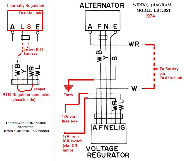
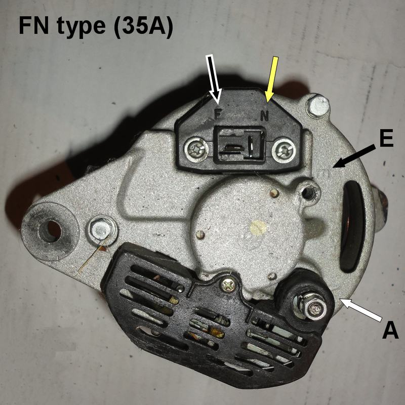
If you install an LR alternator with internal-regulator on a 1200 or other Datsun originally fitted with FN type alternator:
- disconnect the voltage regulator
- in the regulator connector of the engine harness, connect WB wire to WR wire
- connect connect W wire to Y wire
After you disconnect the external voltage regulator, the wires that go down the alternator won't be connected to anything. So the jumper wires re-connect the two alternator wires (L and S) to the correct places.
Logically, you are connecting the "L" (Lamp) terminal of new alternator to "L" (Lamp) wire of the wiring harness. Also connecting "S" (Sense) terminal of new alternator to BAT feed wire so that the alternator will sense the battery voltage at the battery.
Now, it could sense internally (as one-wire alternators do), or via a wire from A to S right on the back of the alternator, so why does it use a Sense wire all the way back to the battery? Because -- in case there are any voltage drops in the wiring -- it will still do consistent regulation. With internal sensing, drops (caused by slight terminal corrosion) will result in slightly low voltage at the battery (even though at the ALT/BAT terminal the voltage output is correct).
Won't the battery run down if the Sense line is connected to a battery feed wire? In other words, shouldn't a switched (IGN) feed wire be connected to the Sense terminal, so when the key is OFF, voltage to the alternator is off? ANSWER: If the diodes in the alternator are good, it won't draw current and run down the battery. Remember, all alternators are connected to 12V all the time (even when key is off) via the ALT/BAT terminal yet the diodes prevent drain-back. In addition, this is how Nissan wired it. It will work either way -- sensing via IGN or via BAT -- but is more fault tolerant via a similar length wire back to battery (see paragraph above).
wiring diagram:
 album
album
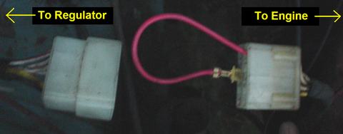
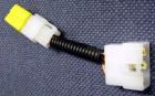 Store-bought version ($30) of jumper wire
You can buy one mail-order from Bprojects. Endo will take care of you, send an email to Bprojects.
![]()
Price: 5,250yen (about $52 USD)
Wiring Explanation
CAUTION: if you jump W to B it will spark, begin to melt and then blow the Fusible Link. Possibly too with other wire combos too depending on if the key is on or off. In any case it should not cause a fire if the Fuses and Fusible Link are all in place. Older Datsun 510 & 521 may not use a Fusible Link, so be sure to connect the right wires.
Voltage Regulator connector
* White: battery feed
* Yellow: Neutral (of original FN alternator)
* White/Red: Lamp (dash CHG or IGN light)
* White/Black: Field (of original FN alternator)
In the conversion:
- Yellow wire is connected to S(battery Sense) terminal of LS alternator, so jumper connects Y to battery (W)
- WB goes to L(Lamp) terminal of LS alternator, so jumper connects WB to dash lamp wire (WR)
You can double-check all this with a voltmeter.
The original 35A alternator should have FN terminals
 album
album
The Internally Regulated alternator should have LS terminals (but same T-connector as FN types)
 album
album
Automatic Choke
NOTE: If your Datsun was factory-equipped with Automatic Choke, jumper is needed at the choke relay connector. The wiring above (two jumpers) will work correctly for charging, but does not fix the choke relay.
METHOD 1: Unplug the Relay, then in the relay connector in the harness, Jump Blue wire to Red wire. This bypasses the relay.
METHOD 2: Retain operation of relay. Cut the Yellow wire at the Relay and run a new wire to the Lamp wire in the harnes. You can unwrap the harness and make the modification neatly inside OR connect it to the long two-wire T-connector harness.
METHOD 3: Obtain new-style relay and rewire engine compartment.
Original Wiring Comparo
With a wiring harness for LT-series alternator the choke relay is Voltage switched (voltage provided by Alternator).
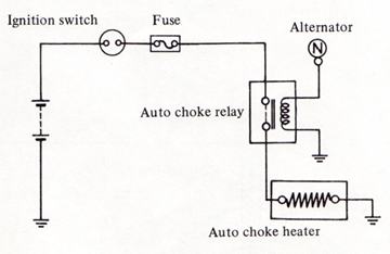
Alternator output will power the relay, activating the choke heater. See Electric Choke Wiring.
With a wiring harness for LR-series alternator, the choke relay is Ground/Earth switched (ground provided by Alternator).
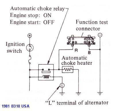
Alternator will ground the relay, de-activating the choke heater.
FN: relay with normally on connection to choke
    relay clicks when engine starts running
LS: relay with normally off connection to choke
    relay clicks when you turn IGN on
Compatibility
The Choke Relay is wired oppositely different on LT-series and LR-series applications. LR harness uses 6-pin relay. B110 harness uses 4-pin relay.
When swapping newer LS-type alternator into older FN-type vehicle, swap N and L lines with a jumper wire. Then the lamp and choke circuits will work as designed.
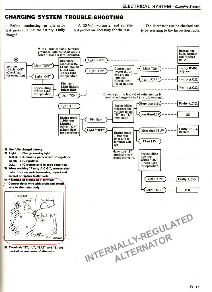
Troubleshooting
1. Check the Voltage at the alternator. Between the BAT terminal and the E terminal (earth/ground) there should be the same V as at the battery. If not, you got a wiring problem.
2. The S terminal should be 12V hot when key is turned to IGN
NOTE: on the B310 with this, S is hot all the time
either way will work
3. The L terminal (Lamp) should be:
- 0V when key is turned OFF
- 12V (more or less) when key is turnd ON
Because the L terminal is the exciter, if your CHG lamp is burned out, the Hitachi LR won't charge.
Factory troubleshooting page
 full
full
Engine Won't Shut Off
If wired incorrectly, the engine will keep running when you turn the key off.
Regulator Still Plugged In
The FN wiring is different from LS wiring. So if you leave the external regulator still plugged in, the wires are incorrect.
It won't cause overcharging, since the LR is internally regulated.
L-S
Lamp: stem of Tee
Sense: head of Tee
F-N
Field: stem of Tee
Neutral: head of Tee
If the external regulator is left plugged in:
- the Neutral line of regulator will be connected to the Sense terminal
- the Field output of regulator will be connected to the Lamp input/output terminal