![[Datsun 1200 encyclopedia]](/wiki/upload/wiki.png)
| Revision as of 06:44, 8 February 2009 Ddgonzal (Talk | contribs) (->Fuse Box) <- Previous diff |
Revision as of 04:25, 26 February 2009 Ddgonzal (Talk | contribs) (->Instrument Panel) Next diff -> |
||
| Line 342: | Line 342: | ||
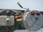
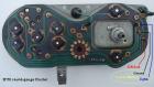
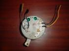
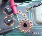
| == Instrument Panel == | == Instrument Panel == | ||
| + | [http://datsun1200.com/modules/myalbum/photo.php?lid=5028 http://datsun1200.com/modules/myalbum/photos/thumbs/5028.jpg] | ||
| === Speedometer === | === Speedometer === | ||
Revision as of 04:25, 26 February 2009
Datsun 1200 wiring is relatively uncomplicated.
WARNING: Wire colors can vary by year, model and country. Please double-check the wiring in your Datsun 1200 before connecting parts according to this article. You don't want to burn something up! Use a voltmeter or test light to confirm the circuit behavior.
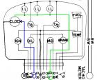
Also see: Wiring Diagram
Wire color codes
| B | Black |
| W | White |
| R | Red |
| Y | Yellow |
| G | Green |
| L | Blue |
BW - Black wire with White stripe
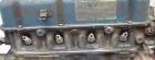
Battery & Main Wiring
Battery has two wires, of course:
- Positive (+). Stock cable is RED. This connects directly to the starter's large connector. A smaller wire runs bout six inches from the terminal to the Fusible Link. See below.
- Negative (-, aka earth/ground). Stock cable is BLACK with Yellow stripe. It connects directly to the engine block at the oil pump. The engine end of this cable also has a smaller black wire. This is the main body ground and connects to the body at the Horn bolt
Main Wiring
There are three important main wires:
- Main ground wire (big battery cable). This bolts to the engine timing cover
- Body ground wire. This goes from the engine end of the Negative battery cable to the body. It's bolted down at the horn bolt. Without this weird problems can happen.
- Red wire at battery '+' terminal. This connects to the Fusible Link ("Main Fuse") about six inches from the battery
WARNING: Do not replace fusible link with a solid wire, or you risk burning up the entire wiring system ... If the fuse blows, figure out why before replacing it. Was there a short in the system, or did it simply overheat due to corroded contacts?
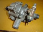
Fusible Link
Use a "FUL 0.5mm2" or better fuse-link. This goes between the battery and the main wiring harness (which also feeds the Alternator output "A" terminal)
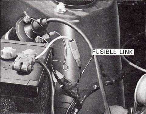
- Part Number 25442-H2500
Improvements
- Relocating battery to back of car. Advantages:
- Make room in engine compartment
- Balance weight of car
- 1200s are nose-heavy, so moving the 28-40 lb battery to the back helps. You need heavy-gauge cable, larger than stock due to the long lenght. Buy a kit with a sealed box, so fumes don't enter car
- Installing a modern new-fangled ground wire "System". There are two opinions:
AFRacer:
The grounding wire kits that people are putting on newer cars DO help out, and in many cases add power! I was a nonbeliever at first until I saw them used and they did add power and when I tore apart my 180SX I understood why it would add power. There are LOTS of electrical parts on newer cars, especially with EFI and distributorless ignitions ...
read moreddgonzal:
You've seen the ads where you install many grounds wires all over the car, sometimes using 'gold' connectors. They don't add horsepower. Not even new cars use this. There are advantages: They do make troubleshooting extremly complex wiring (like in a Mercedes with 47 computers) easier. My advice is don't waste your money on this.[edit:] After reading AFRacer's report above, I wonder if the B110 simply needs a better ground wire. The unibody is a large conductor so there is no problem there, but the stock ground wire is 1) kinda small and 2) in a place where corrosion can cause problems. Try using a thicker wire, grounding the battery and engine to the unibody in a better way (use a thick wire and good connections).
</blockquote>
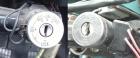
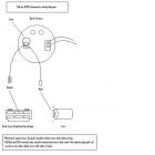
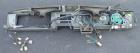
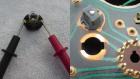
Ignition Switch
The ignition switch bolts to the back of the key cylinder.
 Ignition Switch Comparison
Interchange
B310 has a larger-diameter switch with two mounting lugs. B110 is smaller with one mounting lug. I believe the middle one (the one with the wiring harness) is a B210 switch, and looks like it would plug into the B110 harness, but is wired differently. Beware! I think this is the B210 Auto harness, where the BY wire goes through the auto-trans shifter inhibit switch (can only start car when in Nuetral or Park).
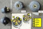
The 1971 switch has four spade terminals. The 1972 and newer adds the "Accessory" position and so has five spade terminals.
TIP: On the back of the switch, each contact is marked ('S', 'IG', etc.). Double-check before replacing to ensure they are the same.
B110 & B210 North American Wiring
| W | B (Battery) |
| BW or | IG (ignition/Run) |
| BW (LW for B210) | ACC (Accessory)
1971 switches didn't have ACC position |
| BY (YB for B210) | S (start) | BR | R (resistor) | </tr>
The switch in the picture with the wires has differently colored wires (WR, L, BL, BW, BY). From these colors and position, I think it is the same wiring as the B310 switch, just different colors.
Wiring Connections
Switch internal connections
| Off | no connections |
| Accessory | Battery (hot) to ACC |
| Run | Battery (hot) to ACC + IG |
| Start | Battery (hot) to IG + Resistor + Start\* |
\*Starting with 1974 automatic models and all newer, ACC is also hot while in the Start position.
Where do the wires go on a stock B110?
| switch terminal | Connects to ... | ||||||||||||||||||||||||||||||||||||||||||||||||||||||||||||||||||||||||||||||||||||||||||||||||||||||||||||
| IG (ignition/run) | This connects to two things:
|