![[Datsun 1200 encyclopedia]](/wiki/upload/wiki.png)
| Revision as of 06:04, 12 June 2010 ddgonzal (Talk | contribs) (->Fusible Link) <- Previous diff |
Revision as of 06:07, 12 June 2010 ddgonzal (Talk | contribs) (->Main Wiring) Next diff -> |
||
| Line 28: | Line 28: | ||
| * Main ground wire (big battery cable). This bolts to the engine timing cover | * Main ground wire (big battery cable). This bolts to the engine timing cover | ||
| * Body ground wire. This goes from the engine end of the Negative battery cable to the body. It's bolted down at the horn bolt. Without this weird problems can happen. | * Body ground wire. This goes from the engine end of the Negative battery cable to the body. It's bolted down at the horn bolt. Without this weird problems can happen. | ||
| - | * Red wire at battery '+' terminal. This connects to the Fusible Link ("Main Fuse") about six inches from the battery<blockquote><hr>WARNING: Do not replace fusible link with a solid wire, or you risk burning up the entire wiring system ... If the fuse blows, figure out why before replacing it. Was there a short in the system, or did it simply overheat due to corroded contacts?<hr></blockquote> | + | * Red wire at battery '+' terminal. This connects to the Fusible Link]] ("Main Fuse") about six inches from the battery<blockquote><hr>WARNING: Do not replace fusible link with a solid wire, or you risk burning up the entire wiring system ... If the fuse blows, figure out why before replacing it. Was there a short in the system, or did it simply overheat due to corroded contacts?<hr></blockquote> |
| Ground/Earth main connections | Ground/Earth main connections | ||
Revision as of 06:07, 12 June 2010
Datsun 1200 wiring is relatively uncomplicated.
WARNING: Wire colors can vary by year, model and country. Please double-check the wiring in your Datsun 1200 before connecting parts according to this article. You don't want to burn something up! Use a voltmeter or test light to confirm the circuit behavior.
Also see: Wiring Diagram
Contents |
Wire color codes
| Code | Color |
| B | Black |
| W | White |
| R | Red |
| Y | Yellow |
| G | Green |
| L | Blue |
BW - Black wire with White stripe
Battery & Main Wiring
Battery has two wires, of course:
- Positive (+). Stock cable is RED. This connects directly to the starter's large connector. A smaller wire runs bout six inches from the terminal to the Fusible Link. See below.
- Negative (-, aka earth/ground). Stock cable is BLACK with Yellow stripe. It connects directly to the engine block at the oil pump. The engine end of this cable also has a smaller black wire. This is the main body ground and connects to the body at the Horn bolt
Main Wiring
There are three important main wires:
- Main ground wire (big battery cable). This bolts to the engine timing cover
- Body ground wire. This goes from the engine end of the Negative battery cable to the body. It's bolted down at the horn bolt. Without this weird problems can happen.
- Red wire at battery '+' terminal. This connects to the Fusible Link]] ("Main Fuse") about six inches from the battery
WARNING: Do not replace fusible link with a solid wire, or you risk burning up the entire wiring system ... If the fuse blows, figure out why before replacing it. Was there a short in the system, or did it simply overheat due to corroded contacts?
Ground/Earth main connections

Make sure they cables are not damaged, and that they are securely fastened. If they are loose, remove and carefully inspect for corrosion. Clean thoroughly if possible, replace if neccesary. This original system will fully support all stock electrical loads.
Fusible Link
Use a "FUL 0.5mm2" or better fuse-link. This goes between the battery and the main wiring harness (which also feeds the Alternator output "A" terminal)
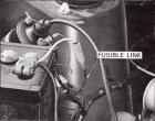
See main article: Fusible Link
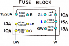
Fuse Box
In addition to the main fuse wire in the engine compartment, there is a main fuse box under the dashboard.
See main article: Fuse Box
Improvements
- Relocating battery to back of car. Advantages:
- Make room in engine compartment
- Balance weight of car
- 1200s are nose-heavy, so moving the 28-40 lb battery to the back helps. You need heavy-gauge cable, larger than stock due to the long lenght. Buy a kit with a sealed box, so fumes don't enter car
- Installing a modern new-fangled ground wire "System". There are two opinions:
AFRacer:
The grounding wire kits that people are putting on newer cars DO help out, and in many cases add power! I was a nonbeliever at first until I saw them used and they did add power and when I tore apart my 180SX I understood why it would add power. There are LOTS of electrical parts on newer cars, especially with EFI and distributorless ignitions ...
read moreddgonzal:
You've seen the ads where you install many grounds wires all over the car, sometimes using 'gold' connectors. They don't add horsepower. Not even new cars use this. There are advantages: They do make troubleshooting extremly complex wiring (like in a Mercedes with 47 computers) easier. My advice is don't waste your money on this.[edit:] After reading AFRacer's report above, I wonder if the B110 simply needs a better ground wire. The unibody is a large conductor so there is no problem there, but the stock ground wire is 1) kinda small and 2) in a place where corrosion can cause problems. Try using a thicker wire, grounding the battery and engine to the unibody in a better way (use a thick wire and good connections).
</blockquote>
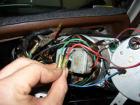
Ignition Switch
The ignition switch bolts to the back of the key cylinder. There is a rectangular wire connector attached to it.
Alternator & Regulator
Our Datsun B110 used -- as with most 1964-1974 cars -- an Alternator with external Voltage regulator.
Alternator Connections
| terminal | Color | Logical Connections |
| A (Alternator) | WR or W | * To Battery + terminal through Fusible Link * To Regulator "A" terminal (W wire) |
| F (Field) | WB | * To Regulator "F" terminal |
| N (neutral point) | Y | * To Regulator "N" terminal * To electric choke relay Y wire |
| E (Earth/ground) | B | * To body ground * To Regulator "E" terminal |
Regulator Connections
| terminal | Color | Logical Connections |
| A (Alternator) | W | * To Alternator "A" terminal (WR or W) |
| F (Field) | WB | * To Alternator "F" terminal |
| N (nuetral point) | Y | * To Alternator "N" terminal * To electric choke relay Y wire |
| E (Earth) | B | * To body ground * To Alternator "E" terminal |
| IG (ignition) | WL (72: W?) | * To fuse box "M" terminal (fused through to IG terminal of ignition switch) |
| L (Light) | WR | * To dash light "IGN" ('72, '73) or "CHG" (1971) |
How the Alternator Dash Light Works
The dash lamp is connected to IGN +. The other side goes to the "L" terminal of the external regulator.
- When the alternator is not putting out current, the "L" terminal is at '-' voltage, so the dash light turns on
- Once the alternator starts putting out current, the "L" terminal is at + voltage, so the light turns off (both sides of the light are at +)
Alternator Upgrade
Many different Datsun alternators and alternators from other makes can easily be fitted to the Datsun 1200.
See main article: Alternator Upgrades
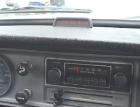
Clock
The clock has a third wire, which goes to the Red/Black wire hanging down from the harness. This is the constant-Hot wire. If you wire to IGN, it only runs when the key is on :-)
Headlights
See Headlight Wiring
Running Lights, Turn Signals, etc
See Lamp Wiring
Tachometer
There are two popular kinds of tachometers, using different wiring
- Induction wiring. There is no actual physical connection of the tachometer to the signal wires. This is what Datsun uses.
- Voltage signal wiring. The tachometer wire is connected to the '-' terminal of the coil (e.g. to the points). This is what most aftermarket tachometers use. Simply wire this in without changing/cutting the existing wiring.
Factory Tachometer
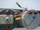
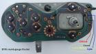
The factory Datsun 1200 tachometer is wired differently than most tachos.
- B - ground - to back of Instrument Cluster
- YR - IG power - to back of Instrument Cluster
- RG - lights (two lights, two wires. Not shown in photo above) to back of Instrument Cluster
- BW - signal loop - to BW wires in dash harness
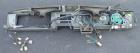
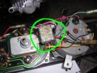
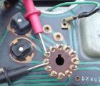
The BW loop of wire is the current induction coil. The ends, logically speaking, go in between the IG terminal of the ignition switch and the single-terminal (non-coil) side of the Ballast Resistor. Note that all IG current goes through this wire, so connect it up in series using the factory connectors (even cars without tachometer have the wiring in place). This is a BW wire along the top of the instrument cluster, seen here inside the yellow circle:

Pull the wire apart at the connectors, and plug the BW loop from the tachometer into it.
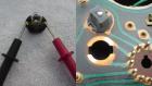
Also in the photo above -- marked as #1 -- are three terminals on the back of the speedometer, just below the left turn signal indicator connector. From top to bottom:
- Lights - RG connect to male spade connector
- Ground - B connect to round flat slide-on connector
- IG power - connect to round bullet connector
- This applies to the Round Gauge dash. The square type has only the Light connector, but a tach can be grounded to one of the gauge housing screws.
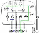
 Factory Tachometer Wiring Diagram and discussion
LATE MODEL UTE
Reportedly, some newer utes do not have the tacho wiring in the harness. In that case, run two new wires from the coil + side back to the dash, connect to the tachometer. See Tacho not working WHY
IGN + --------tacho------ballast--coil +
- If a 120Y (B210) is equipped with a tachometer, the factory tachometer is wired as a part of the ignition system and sends out a pulse to keep the engine firing, however without the tachometer connected the engine will not run with the key in the on position (before the start position) on the ignition switch. If someone was to remove the tachometer the two black wires with white stripes that connect to the tachometer must be connected together.
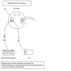
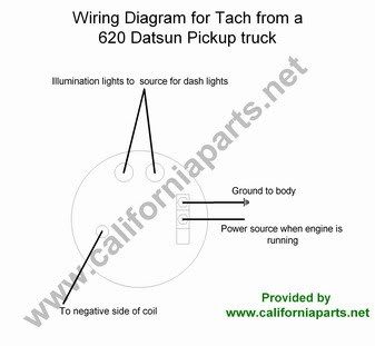
Datsun 620 Tachometer
The tachometer from a Datsun 620 pickup fits exactly into a 1200. The colors and font are more like the PB110 or late model ute.
Wiring is different. The 620 tachometer is triggered by voltage from the negative side of coil.
Aftermarket Tachometer
Most non-Datsun tachometers have four connections:
- coil '-' . usually red or yellow wire
- IG '+' (hot only when key is on) - usually red or white wire
- ground - black wire
- light - often blue wire
So where to connect the wires?
- You can connect IG, Ground and Lights to the three connectors on the back of the speedometer (see above in the Factory Tach section)
- There is no factory interior connection for the coil '-' signal. So you'll need to feed a wire through the firewall and connect it to the coil
Ignition Coil & Distributor
The stock 1200 coil for 1971 and 1972 -- as with nearly all pre-electronic ignition systems -- uses a Ballast resistor to drop the voltage supplied to the coil.
NOTE: The 1973 Wiring Diagram doesn't show a resistor, but it definitely has one.
| Ballast Resistor | Color | Connects To |
| ballast resistor (non-coil side) | BW | IG terminal of ignition switch |
| ballast resistor (coil side, dual-terminal side | BW BR | BR to R terminal of ignition switch\* (and) BW to coil '+' terminal |
| Coil | Color | Connects To |
| Coil '+' | BW | to ballast resistor dual-connector side |
| Coil '-' | B | to distributor points |
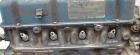
Ballast resistor on right-side Strut tower (left side of photo)

The resistor is just above the coil, and is a white ceramic thing about 2-1/2 inches long.
Starter Motor
Starter just has two wires:
Choke And Carburetor
See:
Interior Lamps
Here's the kinds of smaller lights (other than the headlights) that a Datsun 1200 uses.
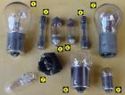 Lights (click for larger size and Details)
 FASTEN SEAT BELT lamp
Instrument Panel
Speedometer
The speedometer has a light for use at night. See the lamp section.
1972 Facelift speedometer has special switch:
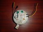
Ute Amplifier Speed Switch
Amplifier for B120 ute Throttle Opener Assembly (see Emission Controls). It's only fitted to the Manual Transmission models.
The speed detecting switch is part of the speedometer assembly and is installed in the speedometer. The amplifier prevents damage to the speed detecting switch which actuate the throttle opener only when the car speed is above 10km/h.Pub No. SM6E-EMC0A0, Page EC-11
Switch has three wires. It looks as if, from these photos:
- Red: Ground ? fits on round-side connector
- Black: -- goes to Red wire coming out of top center of panel
- Green: Unknown
Double-check before using.
USA Amplifier Speed Switch
USA model from 0772 use an amplifier speed switch.
- 25035-H7000 ASSY-AMPLIFIER SPEED SWITCH
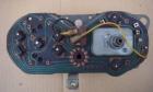
Cluster Gauges
The cluster gauge contains:
- Fuel Gauge (Petrol/Gas gauge)
- Water temperature gauge
- Oil pressure indicator lamp (see "Troubleshooting Oil Light" below)
- Indicators lamp (see "Troubleshooting Dash Lights" below)
- High beam indicator lamp
- Turn Signal indicator lamps
- Brake failure lamp
The coolant/water temperature gauge incorporates a voltage regulator.
- If both the water and fuel gauges are off, suspect the regulator
- If only one gauge is incorrect, suspect a bad connection, usually at the sensor
- Temp sensor at cylinder head (on right side of head, at the very front):
-
- Fuel sensor at fuel tank
- Temp sensor at cylinder head (on right side of head, at the very front):
Fuel Gauge
Back at the Fuel tank, there is a single Yellow (Y) wire on the sender.
- connects to Y wire in the main body harness
- connects to Y wire in the dash wiring harness
- connects to Y wire in the cluster connector
The sender is grounded through the tank body.
Troubleshooting Fuel Gauge
A non-working Fuel gauge is usually one of three things:
- Bad 'sender' (sensor) which is in the fuel tank
- Bad gauge in the dash
- Bad wiring
- Pull the Fuel sensor wire (Yellow) off at fuel tank
- Ground/earth this wire
- turn IGN switch on and observe gauge:
- Gauge still dead. It is not caused by fuel sender. Check for loose wiring, at back of dash, or at dash wiring harness connectors
- Gauge goes to Full. Bad sender
Sender Resistance Check
You can also check the Resistance of the sender. Remove Yellow wire and measure between terminal and bare metal of sender: It should read higher than 10 ohms, but less than 88 ohms. If it is higher or lower than this range, replace the Sender.
Sender Full-Range Test
- Remove Fuel sender from tank. This is fairly easy with Sedan, or with ute after removing inspection cover from tray. Not easy with Coupe.
- With wiring connected to sender, ground/earth the top of the sender to body ground (using a jumper wire)
- Float down, gauge should read below E
- Float up, gauge should read above F
The Fuel Tank Sender (fuel sensor) has a float, and as it rises and falls with the fuel level, it varies the electrical resistance (Ohms) of the sensor. As measured by club members, by moving the float up and down from stop to stop:
- 12 ohms fully up
- 88 ohms fully down
- 35 ohms half full (per Nissan Factory Service Manual)
Dash Lights
These dash lights should light up when you turn the key to ON, before you start the car:
- Oil pressure lamp
- CHG lamp
Both should go out as soon as the engine is started.
These do NOT light up on the pre-start check:
- Brake lamp
- Beam/M.B. lamp
Troubleshooting Oil Light
The sensor for the Oil pressure lamp is on the fuel pump just above the oil filter (left side of A-series engine):
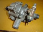
This pump has a T-connector added. The original oil pressure sensor is the spade connector pointing down. A fitting for a mechanical oil pressure gauge is on the other end of the T.
The sensor is an "idiot light". It simply connects the wire to ground when there is oil pressure. So before you start the engine (IGN key on), the Oil lamp bulb is connected to earth/ground through this switch and lights up. As soon as the engine starts and pressure builds, it disconnects the ground circuit so that lamp goes off.
If the lamp never lights up (IGN key on, engine not started):
- Be sure the wire at the oil pump is connected to the connector
- Pull it off and then on again to ensue it is tightly connected. If it is not, you can slightly crimp it with pliers to make it fit better
Check the lamp again. If it still doesn't come on:
- Reach behind the dash and twist the bulb out. If it is burnt out, replace it
If the light comes on (IGN key on, engine not started), but does not go *off* when the engine starts:
- Be sure the wire at the oil pump is connected to the spade connector. If it is off and lying against the engine or body is has a natural earth/ground and so won't work correctly
If that is not the problem:
- Disconnect the wire at the pump. Place it where it doesn't touch metal. Test the light again (with IGN key on):
- Light is off: replace the sensor. One from most any Datsun model will fit.
- Light stays on: You've got an unusual problem with the wiring or dash gauge cluster
This test is for functionality of the light. You don't need to start the engine to test this. If the light checks out OK, but there is no pressure or you suspect so, see Lubrication System Diagnoses.
Troubleshooting Dash Lights
After more than 30 years, these sometimes don't work. Could be a burnt-out bulb, corroded contact, or broken wire (turn signal indicators use wires).
 Testing dash lights
 Cleaning dash light contacts