![[Datsun 1200 encyclopedia]](/wiki/upload/wiki.png)
| Revision as of 09:04, 16 July 2016 ddgonzal (Talk | contribs) (->Cylinder Head and Valve 119) <- Previous diff |
Revision as of 09:43, 16 July 2016 ddgonzal (Talk | contribs) (->Assembly 132) Next diff -> |
||
| Line 122: | Line 122: | ||
| 7-4 組立 Assembly | 7-4 組立 Assembly | ||
| - | page 132{{PhotoBorder|A14E|132.jpg}} | + | <span id="132">page 132</span>{{PhotoBorder|A14E|132.jpg}} |
| + | |||
| + | 刻印を上側に向ける Direction stamped on the inside | ||
| + | トップリング Top Ring | ||
| + | セカンドリング 2nd Ring | ||
| + | オイルリング Oil Ring | ||
| + | <img size=400>http://i297.photobucket.com/albums/mm219/ddgonzal/A14E/132a.jpg</img> | ||
| + | ピストンリング組付 Piston Ring Assembly | ||
| + | |||
| + | シリンダー ヘッド側 (ペイントが?布されている) | ||
| + | Cylinder head side (paint is? Cloth) | ||
| + | <img size=400>http://i297.photobucket.com/albums/mm219/ddgonzal/A14E/132d.jpg</img> | ||
| page 133{{PhotoBorder|A14E|133.jpg}} | page 133{{PhotoBorder|A14E|133.jpg}} | ||
Revision as of 09:43, 16 July 2016
Nissan Factory service manual for the A14E fuel injected engine, 1978 edition.
A14E Service Manual
A14E Service Manual Part 2 Engine Overhaul & Service Data
You can help us out! If you can type Japanese, please click Edit and type in the text. Also need help translating. Thanks!
 |
A型 エンジン
|
A-series Engine
(1978 Standards Conforming Car)
|
Contents |
Engine Overhaul 114
7. エンジン本体のオーバーホール Engine overhaul
Overhaul Notes 114
7-1 オーバーホール上の注意事項
page 114Template:PhotoBorder
Disassembly 115
7ー2 分解 Disassembly
page 115Template:PhotoBorder
page 116Template:PhotoBorder
page 117Template:PhotoBorder
page 118Template:PhotoBorder
Inspection, Correction, Replacement 119
7-3 点検、修正、交換 Inspection, Correction, Replacement
Cylinder Head and Valve 119
(1) シリンダー ヘッド及びバルブ
page 119Template:PhotoBorder
page 120Template:PhotoBorder
page 121Template:PhotoBorder
page 122Template:PhotoBorder
Page 123 |
⑥ バルブ シート インサート
標準締代 0.064 ~ 0.096 mm (参考) ⑦ バルブ スプリング
         (単位:mm)
       ンナー アウター
自由長      43.5 46.0
自由長限度    41.5 44.5
直角定規で各スプリングの直角度を測定し、 スプリングのたおれが限度以上のときは、交 換する。ただし直角度はスプリング上面と直 角定規のすき間で表れす。 (単位:mm) 直角度限度 (インナー アウター共) 1.3 |
6. Valve seat insert
Interference Fit
  0.064 ~ 0.096 mm (Reference)
7. Valve spring
                  (Unit: mm)
                  Inner Outer
Free length        43.5  46.0
Free length limit  41.5  44.5
The squareness of each spring is measured at a right angle ruler, of the spring collapse when the above limit, be replaced. However straight angle to appear in the gap of the spring top and square. (Unit: mm) Straightness limit (Inner, outer both) 1.3 |
|
バルブ スプリング張力測定
|
直角定規 Square |

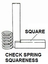 バルブ スプリング直角度の点検
Check spring squareness
バルブ スプリング直角度の点検
Check spring squareness
Also see: Valve spring testing
Cylinder Block 124
(2) シリンダー ブロック
page 124Template:PhotoBorder
Piston, Piston Ring, Conrod 125
(3) ピストン、ピストン リング、コンロッド
page 125Template:PhotoBorder
page 126Template:PhotoBorder
page 127Template:PhotoBorder
Crankshaft, Main Bearing 128
(4) クランクシャフト、メーン ベアリング
page 128Template:PhotoBorder
page 129Template:PhotoBorder
Camshaft 130
(5) カマシャフト
page 130Template:PhotoBorder
Other Components 131
(6) その他の構成部品
page 131Template:PhotoBorder
Assembly 132
7-4 組立 Assembly
page 132Template:PhotoBorder
刻印を上側に向ける Direction stamped on the inside トップリング Top Ring セカンドリング 2nd Ring オイルリング Oil Ringピストンリング組付 Piston Ring Assembly
シリンダー ヘッド側 (ペイントが?布されている)
Cylinder head side (paint is? Cloth)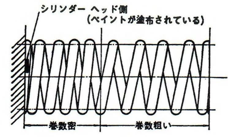
page 133Template:PhotoBorder
page 134Template:PhotoBorder
page 135Template:PhotoBorder
page 136Template:PhotoBorder
page 137Template:PhotoBorder
page 138Template:PhotoBorder
page 139Template:PhotoBorder
page 140Template:PhotoBorder
Service Data 141
8. サ=ビス データ Service Data
Standard Bolt, Nut Tightening Torque 141
8-1 標準ボルト、ナット締付トルク Standard Bolt, Nut Tightening Torque
page 141Template:PhotoBorder
Engine Torque Specs 142
8-2 主なエンジン関係締付トルク
page 142Template:PhotoBorder
Service Data 143
8-3 サービズ データ
page 143Template:PhotoBorder
page 144Template:PhotoBorder
page 145Template:PhotoBorder