![[Datsun 1200 encyclopedia]](/wiki/upload/wiki.png)
Download: Datsun 1200 Competition Suspension Manual Online: PDF
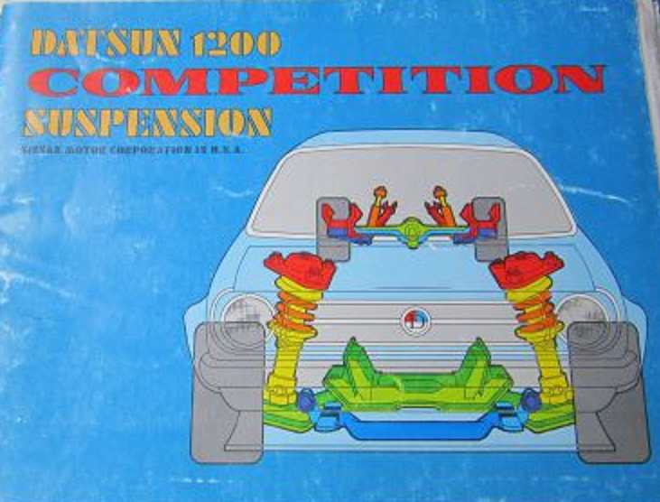
Overview
This manual was sold by the Datsun Competition parts catalog:
The ultimate race car suspension book. It contains step-by-step instructions, dozens of detailed drawings, and most important, a complete set of working blueprints illustrating every piece necessary to duplicate the suspension of Datsun's 1200 C Sedan Championship car. The blueprints are full scale and complete in every detail. Every dimension, specification and material requirement is called out and all modifications are clearly outlined. The suspension system illustrated in this book was designed to be both inexpensive and easy to fabricate, and it has proven itself repeatedly in competition. Note also, that while the project car illustrated in this manual is a Datsun 1200, the principals outlined will apply to any car with a MacPherson strut front suspension and a live rear axle.
Foreward
Page 1 Page 2
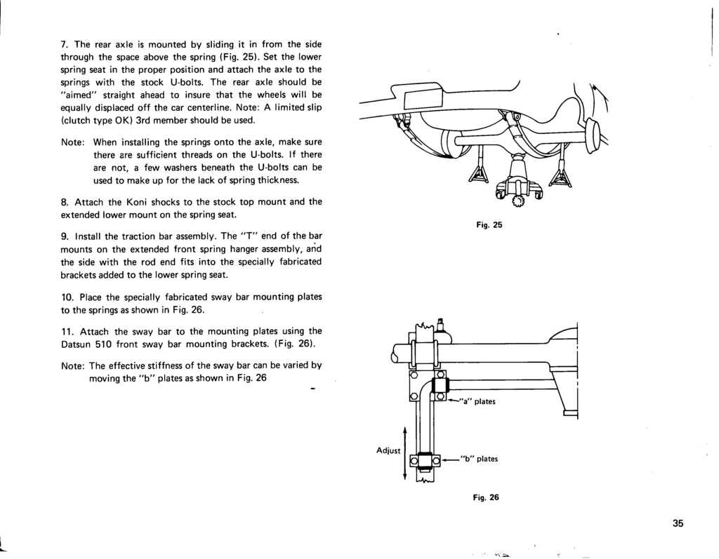
The Datsun 1200 development program was initiated by the Datsun Competition Department to improve the overall performance potential of the 1200 chassis for SCCA C sedan competition. The project had three primary goals:
- To obtain maximum chassis performance at minimum cost.
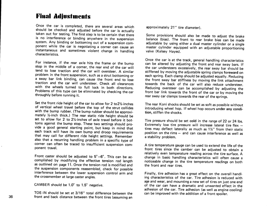
- To produce a handling package requiring a minimum number of chassis modifications, i.e. a bolt-on competition suspension kit.
- Winning the National C sedan championship
At the end of the first season all three goals were attained, and you can benefit from the results of this extensive development program.
The project was guided by Dick Roberts, head of the Datsun Competition Department, using the George Eickhoff 1200 sedan as the development car. The 1200 suspension was prepared by Trevor Harris and the car was driven by Don Devendorf. During the first season of development, Devendorf captured every pole position and won every race he entered. He ended the year with a pole position and class win at the Nationals at Road Atlanta. This book is a step by step guide to duplicating that winning set up.
Before fabricating any parts, it is essential that you read all the instructions and study the blueprints carefully. Beside some of the figure numbers throughout the book you will find a "zone" number which will indicate the position of that particular part on the enclosed blueprints. Note that many suspension components are left stock with no modifications whatsoever. The front crossmember, lower control arms (with stock rubber bushings), the steering links, and tie rod ends all remain stock and have held up well in competition.
Notice that the rear axle depends on the springs for lateral location, and uses no panhard rod, watts linkage, or any other lateral locator, Relatively simple traction bars prevent axle wind-up and provide the fore aft location.
This chassis set up has repeatedly proved itself in competition, yet remains relatively simple and inexpensive to fabricate. All the information necessary to duplicate Eickhoff's 1200 is provided. The rest is up to you.
OCTOBER 1975
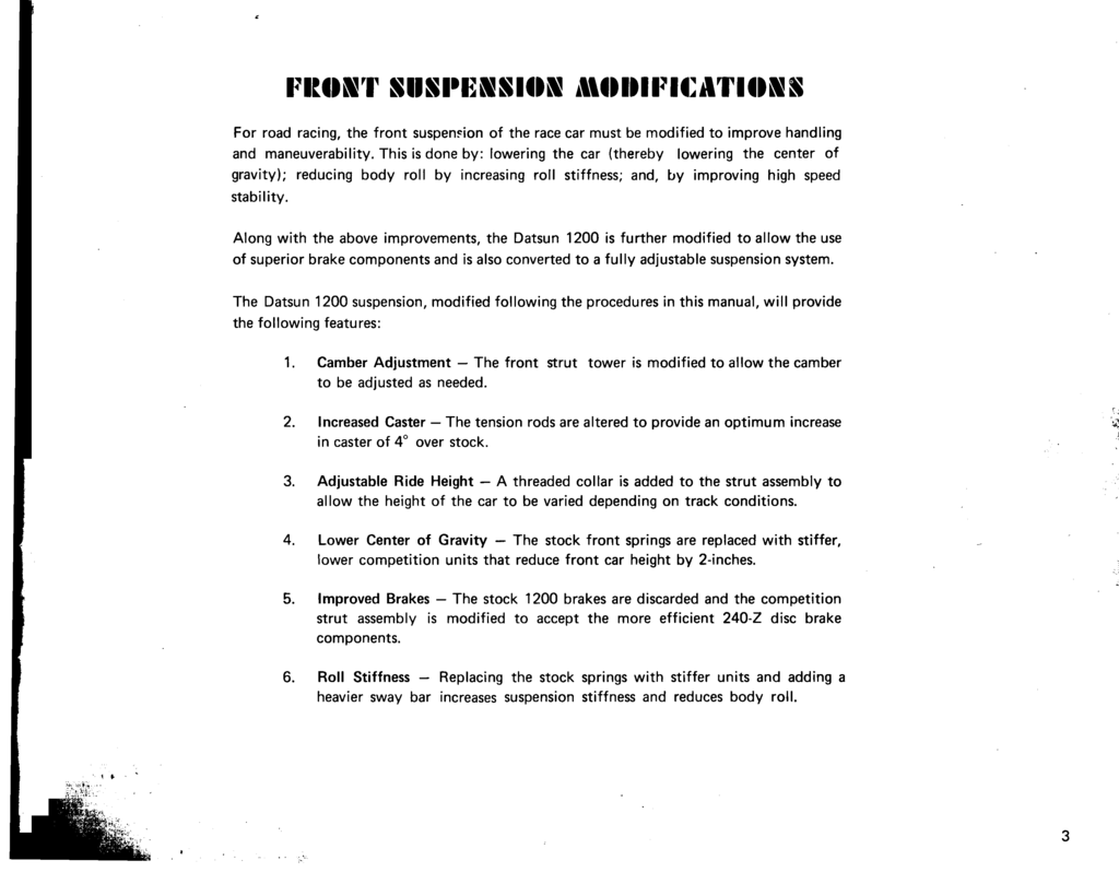
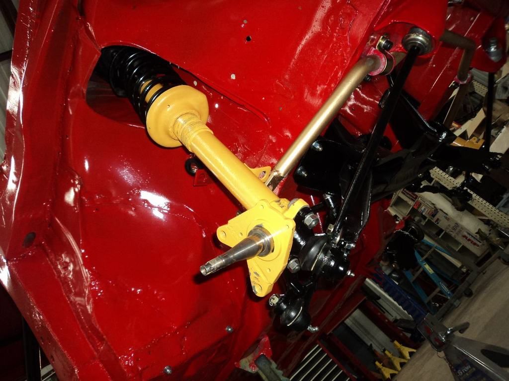
Front Suspension Modifications
For road racing, the front suspension of the race car must be modified to improve handling and maneuverability. This is done by: lowering the car (thereby lowering the center of gravity); reducing body roll by increasing roll stiffness; and, by improving high speed stability.Along with the above improvements, the Datsun 1200 is further modified to allow the use of superior brake components and is also converted to a fully adjustable suspension system.
The Datsun 1200 suspension, modified following the procedure in this manual, will provide the following features:
1. Camber Adjustment the front strut tower is modified to allow the camber to be adjusted as needed. 2. Increased Caster the tension rods are altered to provide an optimum increase in caster of 4° over stock.
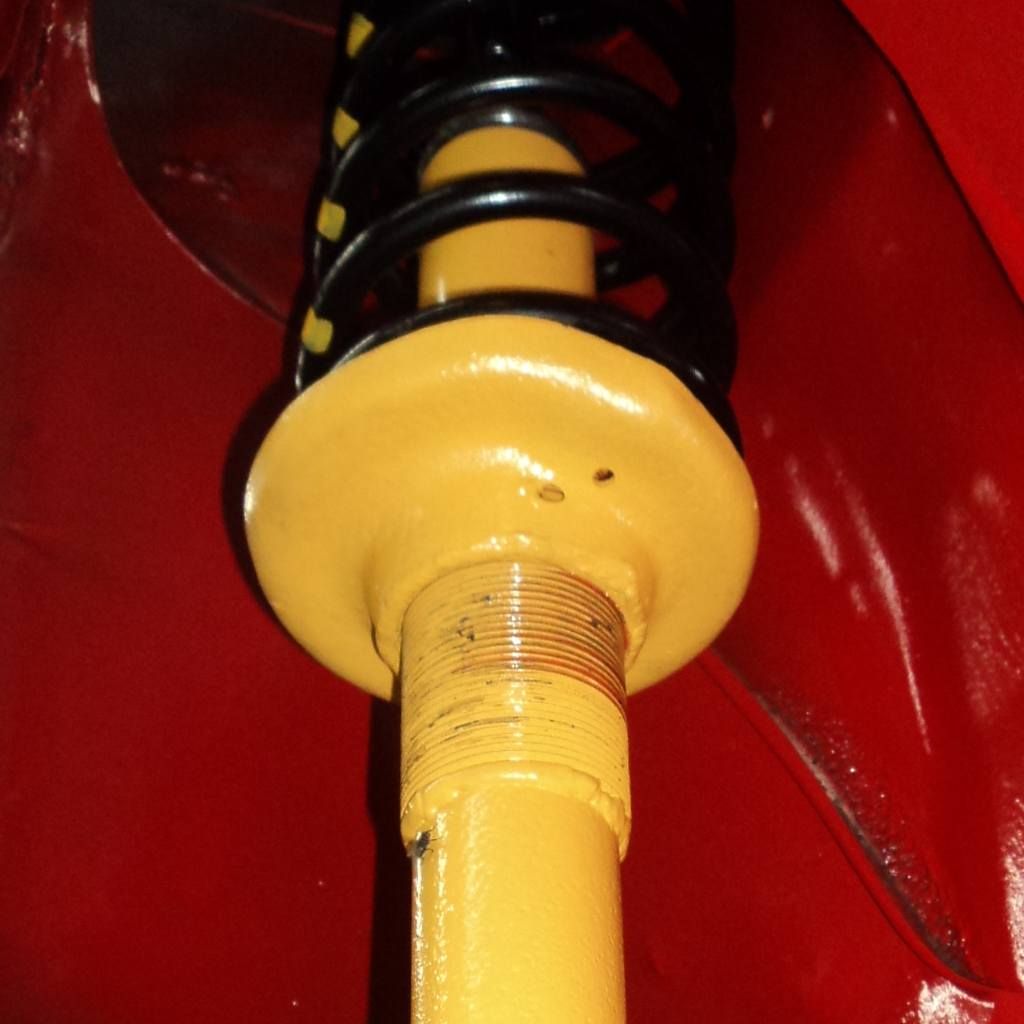
3. Adjustable Ride Height A threaded collar is added to the strut assembly to allow the height of the car to be varied depending on track conditions.
4. Lower Center of Gravity The stock front springs are replaced with stiff, lower competition units that reduce front car height by 2 inches.
5. Improved Brakes The stock 1200 brakes are discard and the competition strut assembly is modified to accept the more efficient 240-Z disc brake components.
6. Roll Stiffness Replacing the stock springs with stiffer units and adding a heavier sway bar increases suspension stiffness and reduces body roll.
Page 3
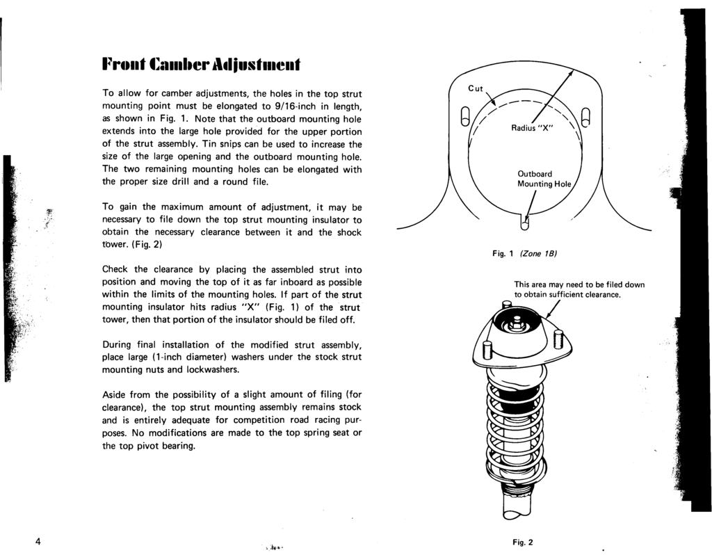
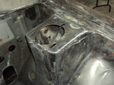
Front Camber Adjustment
Front Camber AdjustmentTo allow for camber adjustments, the holes in the top strut mounting point must be elongated to 9/16-inch in length, as shown in Fig. 1. Note that the outboard mounting hole extends into the large hole provided for the upper portion of the strut assembly. Tin snips can be used to increase the size of the large opening and the outboard mounting hole. The two remaining holes can be elongated with the proper size drill and a round file.
To gain the maximum amount of adjustment, it may be necessary to file down the top strut mounting insulator to obtain the necessary clearance between it and the shock tower. (Fig. 2)
Check the clearance by placing the assembled strut into position and moving the top of it as far inboard as possible within the limits of the mounting holes. If part of the strut mounting insulator hits radius "X" (Fig. 1) of the strut tower, then that portion of the insulator should be filed off.
During final installation of the modified strut assembly, place large (1-inch diameter) washers under the stock strut mounting nuts and lockwashers.
Aside from the possibility of a slight amount of filing (for clearance), the top strut mounting assembly remains stock and is entirely adequate for competition road racing purposes. No modifications are made to the top spring seat or the top pivot bearing.
Fig. 1
Fig. 2
Page 4
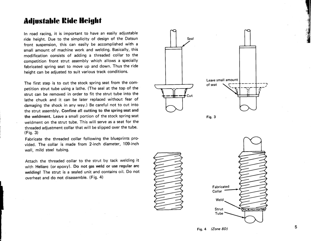
Adjustable Ride Height
Page 5
Page 6
Modified Strut Caliper Mount
Page 7
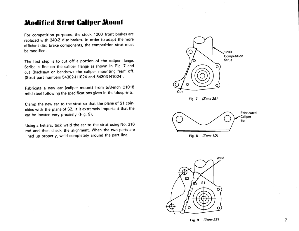
For competition purposes, the stock 1200 front brakes are replaced with 240-Z disc brakes. In order to adapt the more efficient disc brake components, the competition strut must be modified.
The first step is to cut off a portion of the caliper flange. Scribe a line on the caliper flange as shown in Fig. 7 and cut (hacksaw or bandsaw) the caliper mounting "ear" off. (Strut part numbers 54302-H1024 and 54303-H1024).

Fig. 7 (Zone 2B) Cut 1200 Competition Strut
Fabricate a new ear (caliper mount) from 5/8-inch C1018 mild steel following the specifications given in the blueprints.
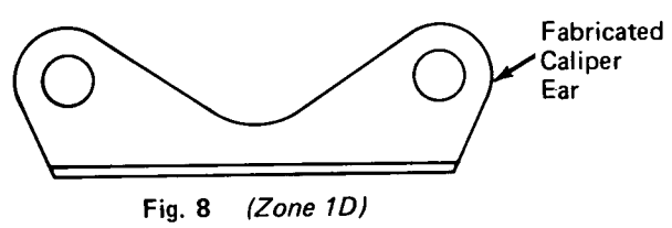
Fig. 8 (Zone 1D) Fabricated Caliper Ear
Clamp the new ear to the strut so that the plane of S1 coincides with the plane of S2. It is extremely important that the ear be located very precisely (Fig. 9).
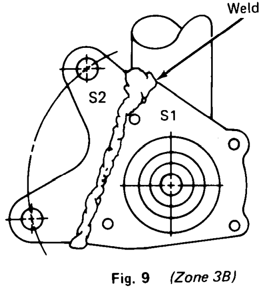
Fig. 9 (Zone 3B) S1 S2 Weld
Using a heliarcᵂ, tack weld the ear to the strut using No. 316 rod and then check the alignment. When the two parts are lined up properly, weld completely around the part line.
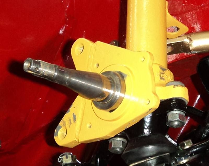
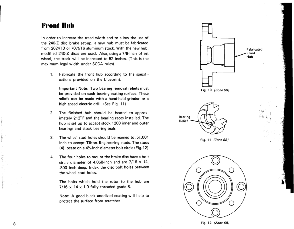
Front Hub
Page 8
Disc Brake Rotor
Page 9
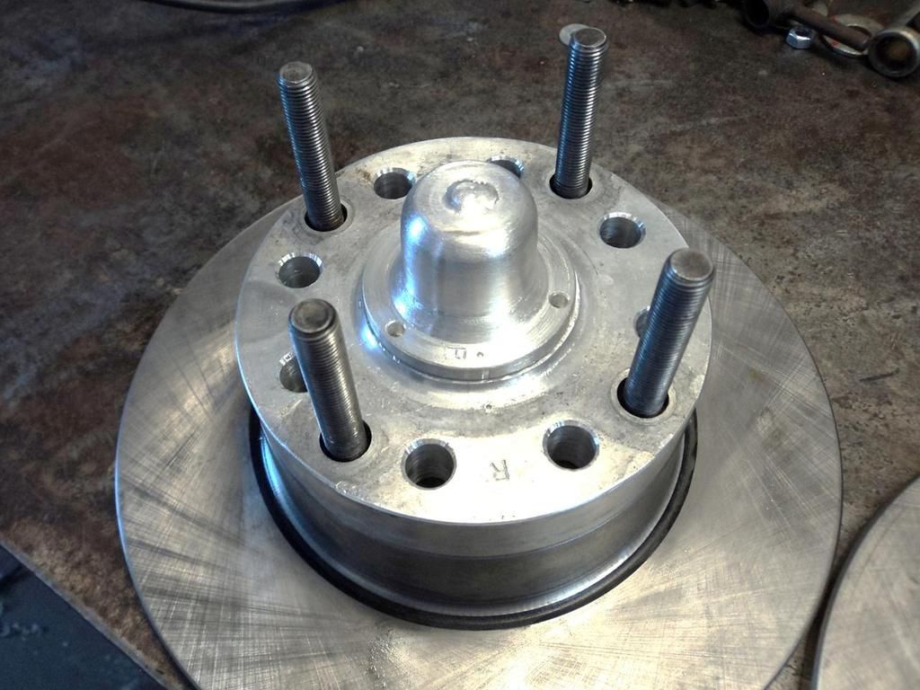
The disc brake rotor is a modified, stock 240-Z unit (part number 40206-E4101ᴳ).
The first step in adapting the 240-Z rotor to the 1200 is to machine the outside diameter of the rotor to 10.312+-.025 [261.92 mm +- .635 mm. NOTE: 240Z stock rotor diameter is 271mm]
Machine radius "X" (see Fig. 13) to clear the hub flange radius (Radius —.250)
Machine surface S, Fig. 13, to remove casting marks (optional)

Fig. 13 (Zone 4C) Surface S Radius X
Note: The rotor inside diameter must clear the hub by .002 to .004-inch to allow for heat expansion.
Rotor mounting bolts should be fully threaded, 1.0-inch shank length, grade 8. Torque the bolts to 40 lbs. and secure with Lock-Tite and safety wireᵂ (Fig. 14).
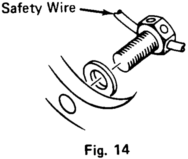
Fig. 14 Safety Wire
240-Z Caliper Modification
Page 9
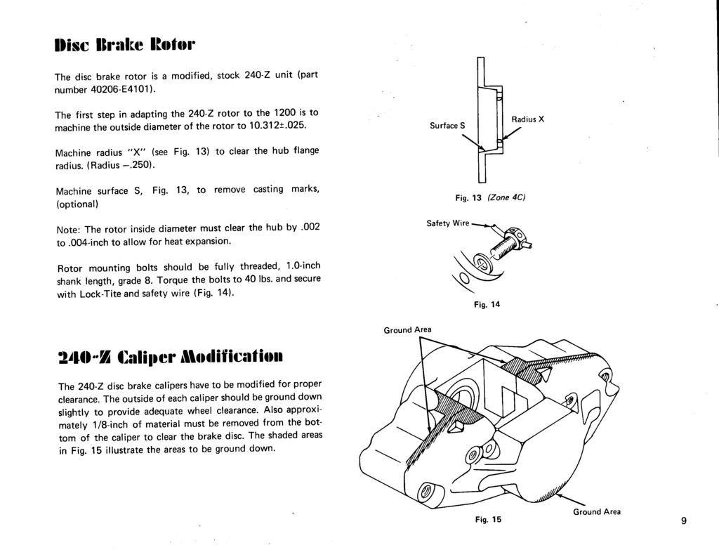
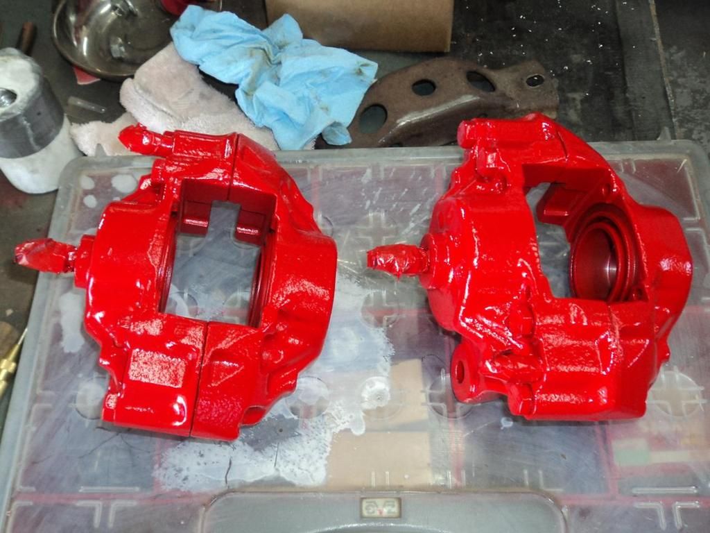
The 240-Z disc brake calipers have to be modified for proper clearance. The outside of each caliper should be ground down slightly to provide adequare wheel clearance. Also approximately 1/8-inch of material must be removed from the bottom of the caliper to clear the brake disc. The shaded areas in Fig. 15 illustrate the areas to be ground down.

Fig. 15 Ground Area
Page 10
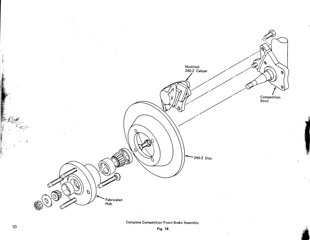
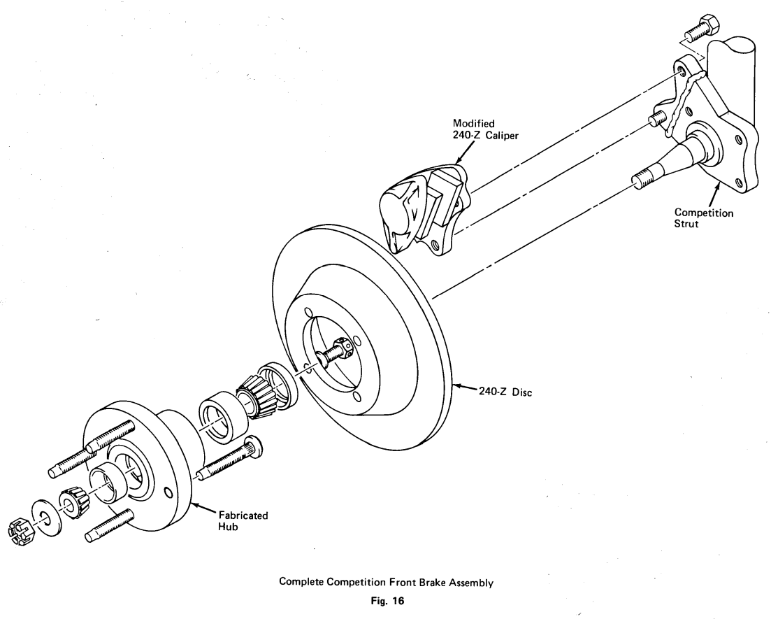
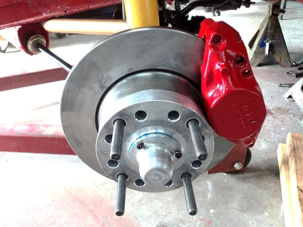
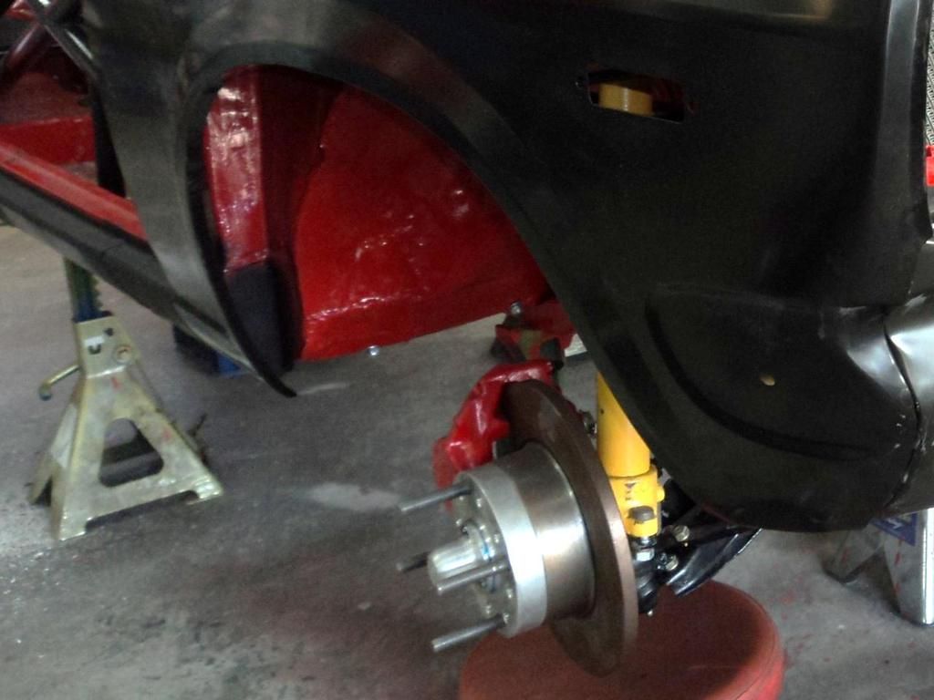
Fig. 16 Complete Competition Front Brake Assembly
Modified 240-Z Caliper Competition Strut 240-Z Disc Fabricated Hub
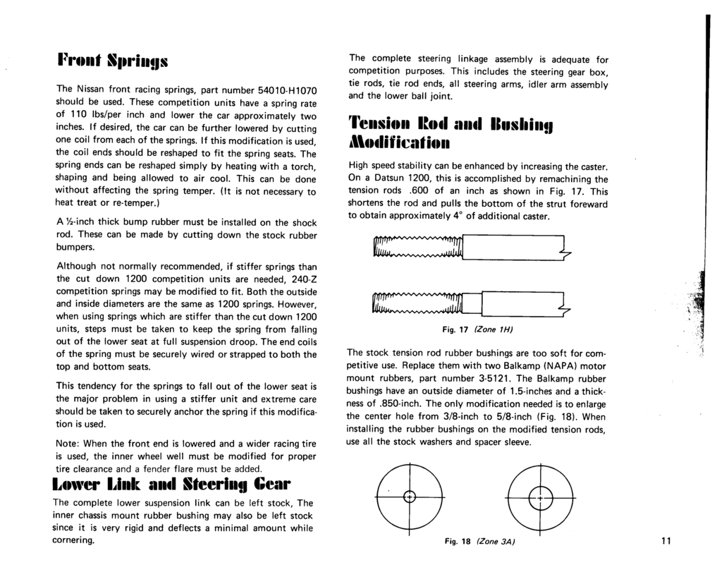
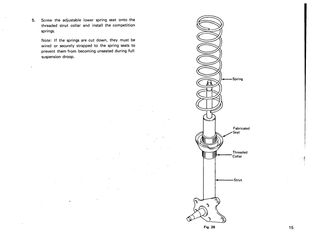
Front Springs
Page 11
Lower Link and Steering Gear
The complete lower suspension link can be left stock. The inner chassis mount rubber bushing may also be left stock since it is very rigid and deflects a minimal amount while cornering.
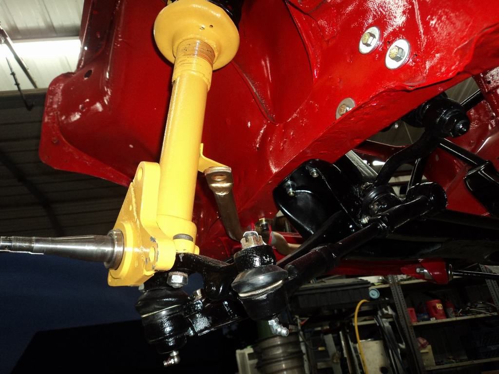
The complete steering linkage assembly is adequate for competition purposes. This includes the steering gear box, tie rods, tie rod ends, all steering arms, idler arm assembly and the lower ball joint.
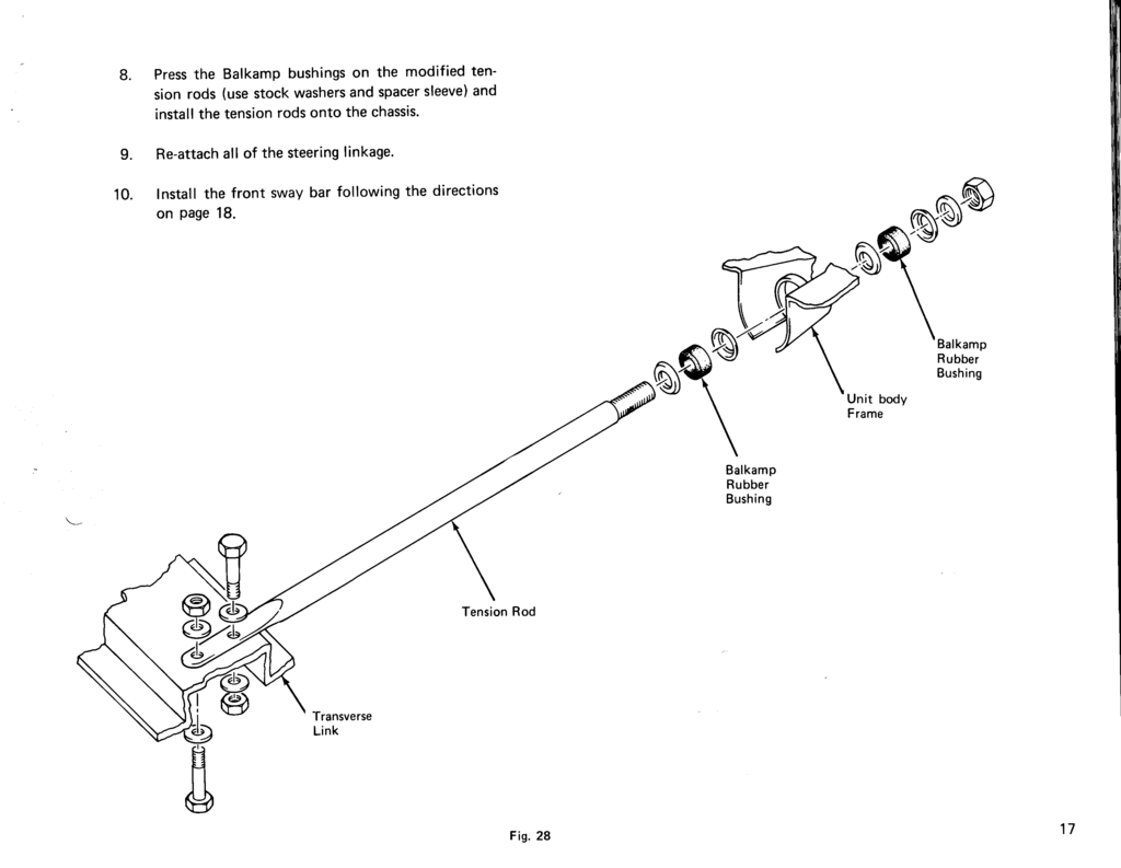
Tension Rod and Bushing Modification
Page 11

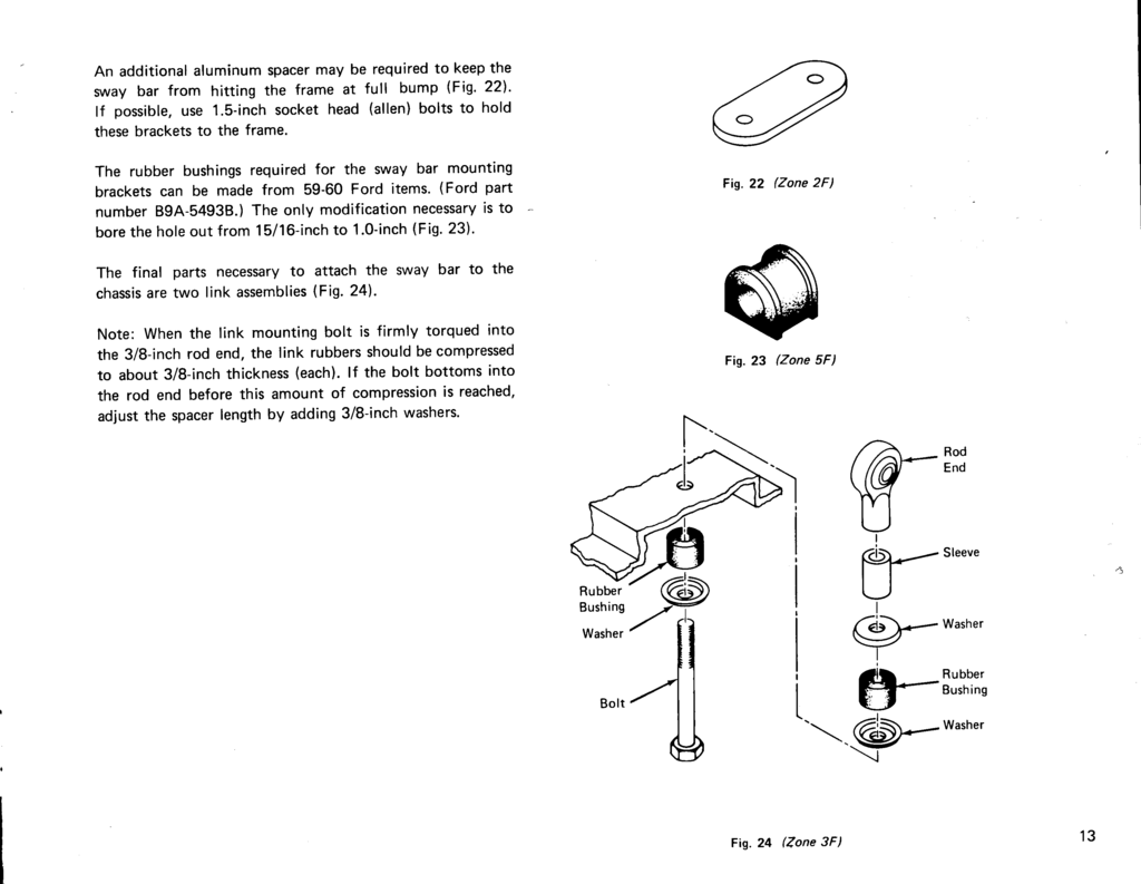
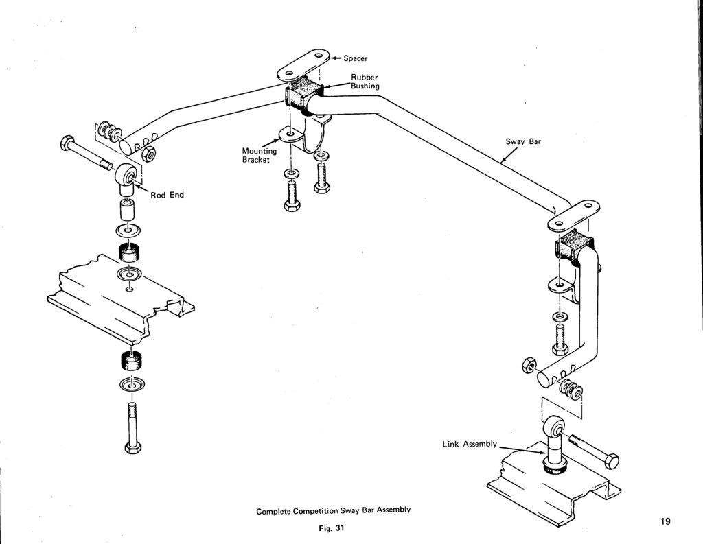
Sway Bar Assembly
Page 12
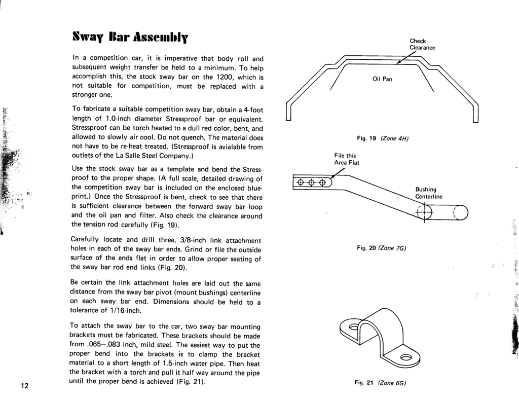
Page 13
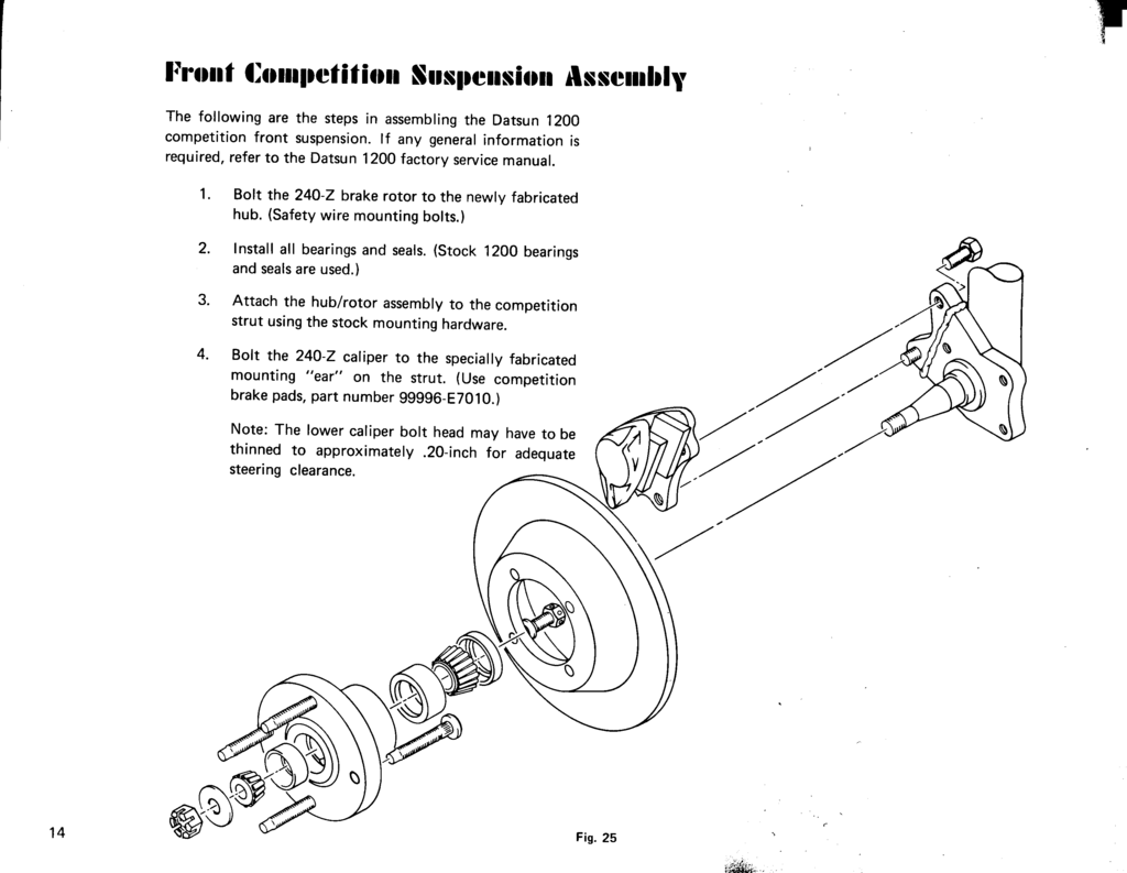
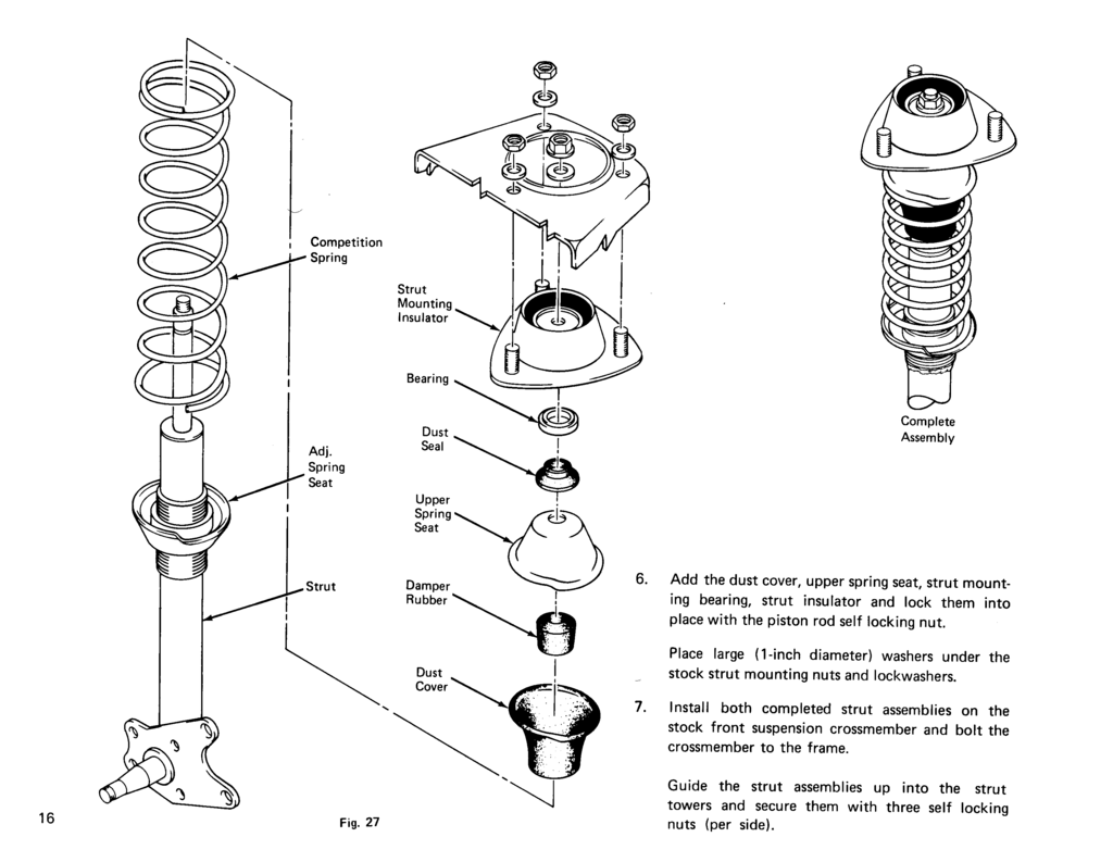
Front Competition Suspension Assembly
Page 14
Page 15
Page 16
Page 17
Sway Bar Installation
Page 18
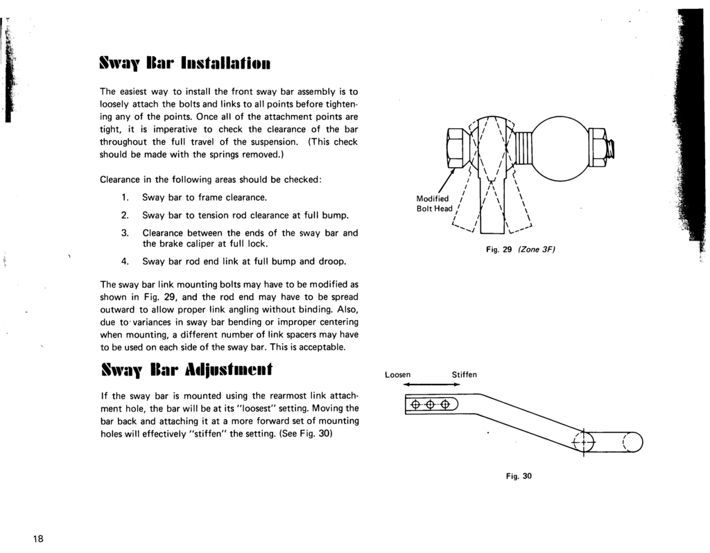
Sway Bar Adjustment
Page 18
Page 19
page 20 (blank page)

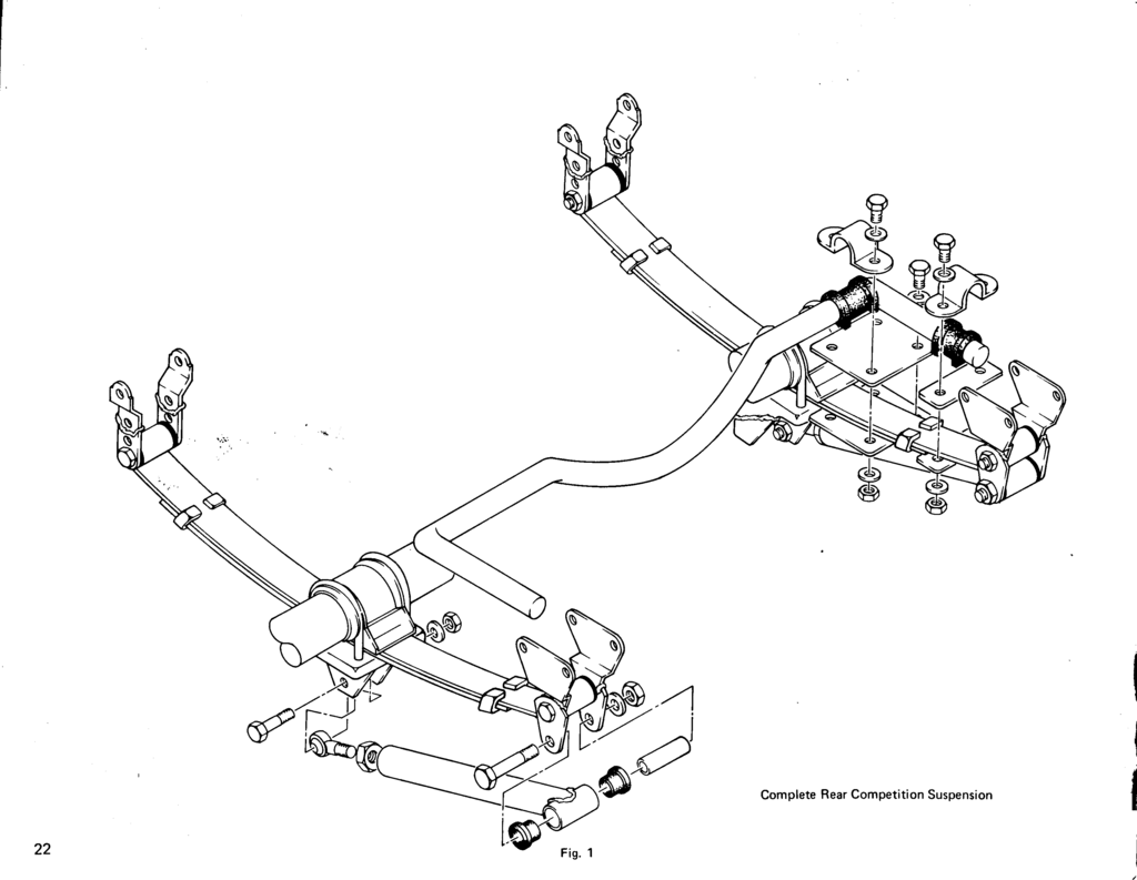
Rear Suspension Modifications
Page 21
Like the front, the rear suspension must be modified to improve handling and maneuverability. Steps must also be taken to see that traction is improved to insure that all the available power "gets to the ground."In order to improve handling and traction, the modifications illustrated in this manual are designed to achieve the following results:
1. Control of lateral and fore-and-aft rear axle movement. 2. Prevent spring wrap-up and improve traction.
3. Increase spring rate.
4. Provide a fully adjustable suspension (shocks, ride height, roll stiffness).
5. Lower car height.Since the front and rear suspensions are dissimilar, different steps are needed to achieve the desired results in the rear. These modifications include:
1. Shocks and reworked lower shock mount. 2. Spring modification.
3. Front spring eye bushings.
4. Front spring hanger chassis mount bushings.
5. Traction arm assembly.
6. Reworked rear spring shackle assembly.
7. Sway bar assembly.
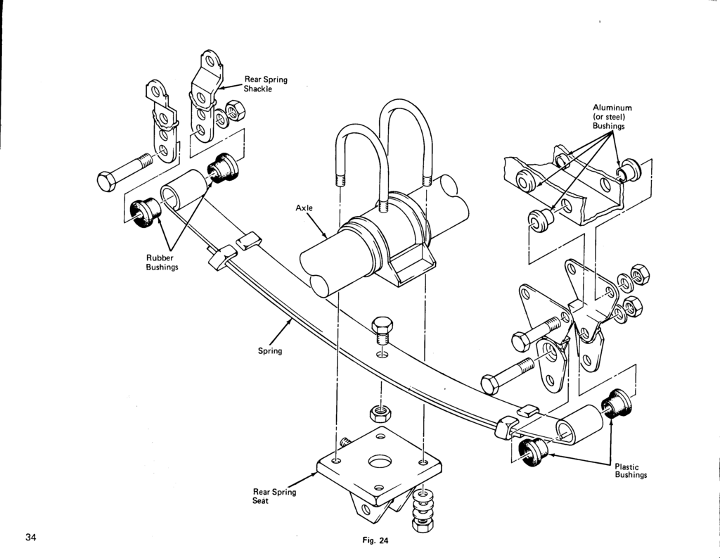
page 22 Fig. 1 Complete Rear Competition Suspension

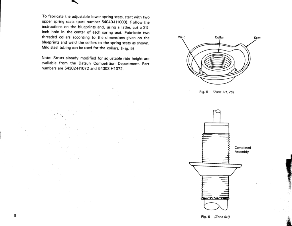
Rear Spring Modification
Rear Spring Modification
The original rear springs are replaced with modified Datsun 1200 Competition units, Part Number 55020-H1024. The competition spring assembly contains three leaves held together by a single bolt.
Before installation, both of the competition springs are modified by removing the bolt and discarding the bottom (short) leaf. Then simply bolt thetwo remaining spring leaves back together. This modification will result in a spring rate reduction of approximately 25% from the unaltered competition spring assembly, but an increas of approximately 10% over the stock 1200 assembly.
Page 23
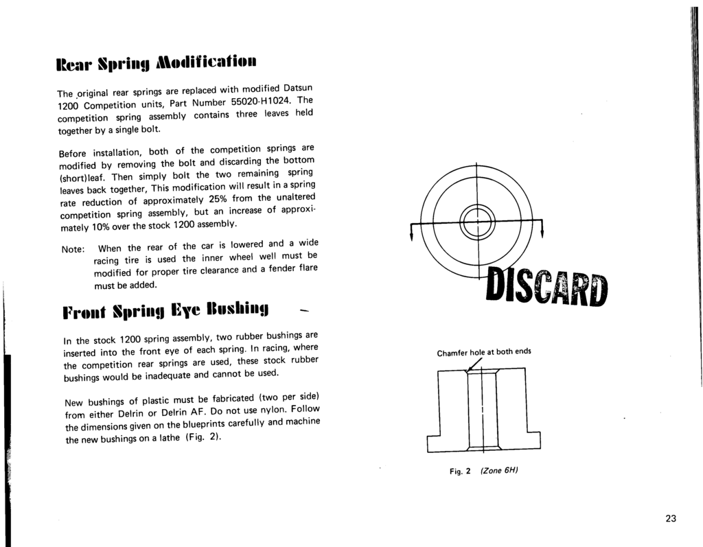
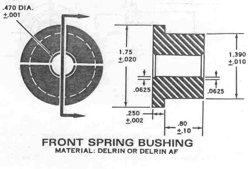
Front Spring Eye Bushing
Page 23
Compare to Comp manual:
Shocks and Reworked Lower Mount
Page 24
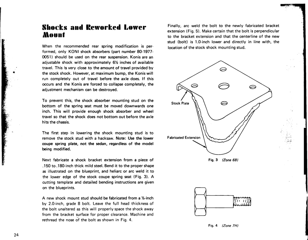
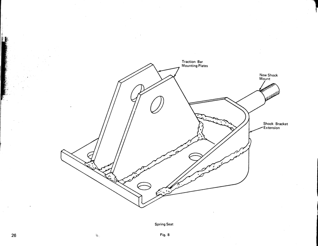
When the recommended #rear spring modification is performed, only KONI shock absorbers (part number 80-1977-0051) should be used on the rear suspension. Konis are an adjustable shock with approximately 6-1/2 inches of available travel. This is very close to the amount of travel provided by the stock shock. However, at maximum bump, the Konis will run completely out of travel before the axle does. If this occurs and the Konis are forced to collapse completely, the adjustment mechanism can be destroyed.
To prevent this, the shock absorber mounting stud on the bottom of the spring seat must be moved downwards one inch. This will provide enough shock absorber and wheel travel so that the shock does not bottom out before the axle hits the chassis.
The first step in lowering the shock mounting stud is to remove the stock stud with a hacksaw. Note: use the lower coupe spring plate, not the sedan, regardless of the model being modified.
Next fabricate a shock bracket extension from a piece of .150 to .180-inch thick mild steel. Bend it to the proper shape as illustrated on the blueprint, and heliarc or arc weld it to the lower edge of the stock coupe spring seat (Fig. 3). A cutting template and detailed bending instructions are given on the blueprints.
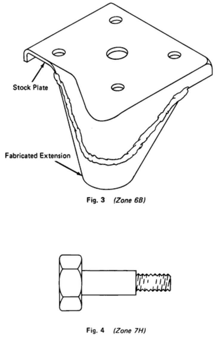
A new shock mount stud should be fabricated from a 1/2-inch by 2.0-inch, grade 8 bolt. Leave the full head thickness of the bolt unaltered as this will properly space the shock away from the bracket surface for proper clearance. Machine and rethread the nose of the bolt as shown in Fig. 4.
Finally, arc weld the bolt to the newly fabricated bracket extension (Fig. 5). Make certain that the bolt is perpendicular to the bracket extension and that the centerline of the new stud (bolt) is 1.0-inch lower and directly in line with, the location of the stock shock mounting stud.
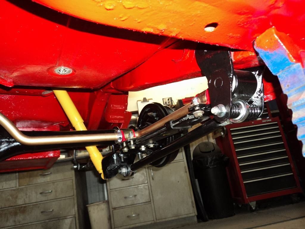
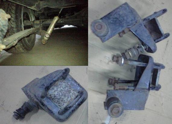
EDITOR'S NOTE: here is a photo of similar mod for a shock with 2" longer compression length:
Rear Traction Bar Mount
Page 25
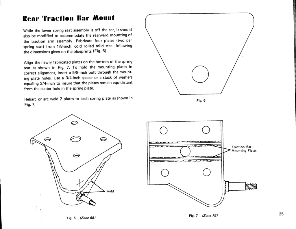
Page 26
Front Spring Hanger Mount Chassis Bushing
Page 27
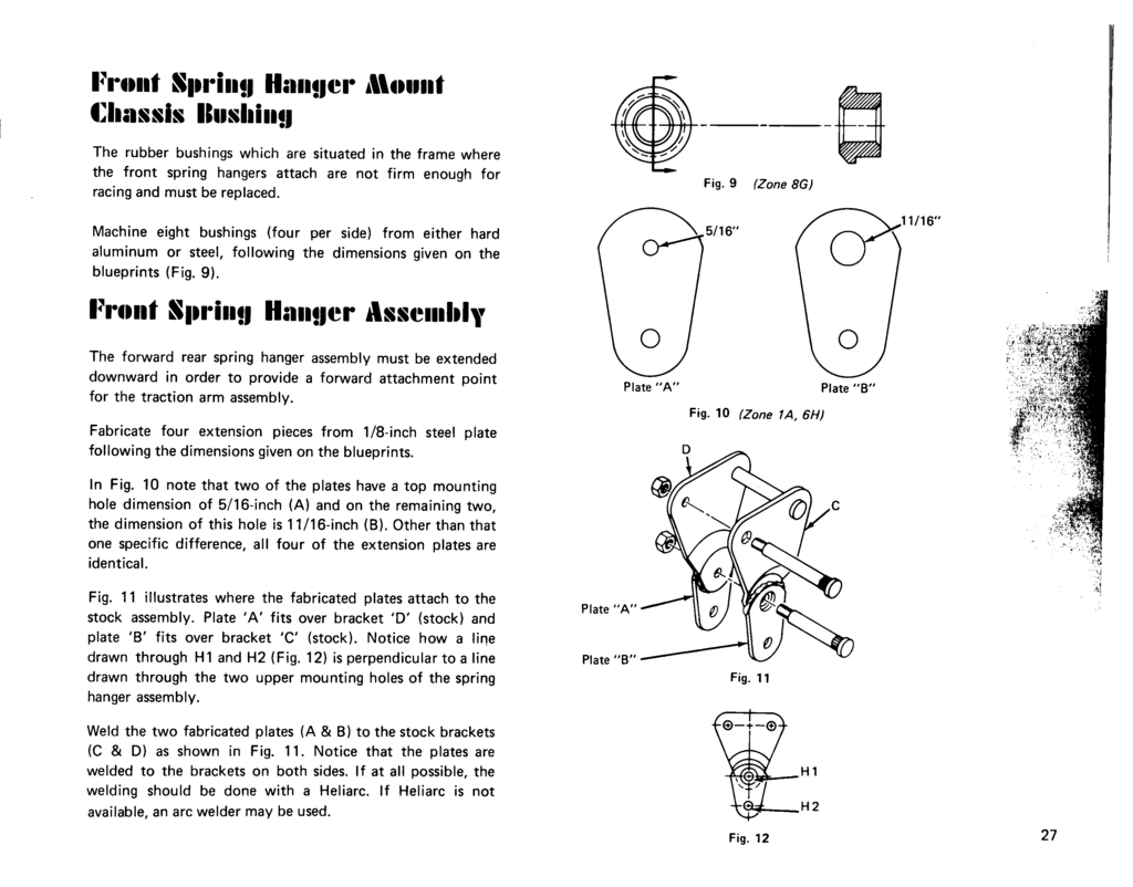
Front Spring Hanger Assembly
Page 27
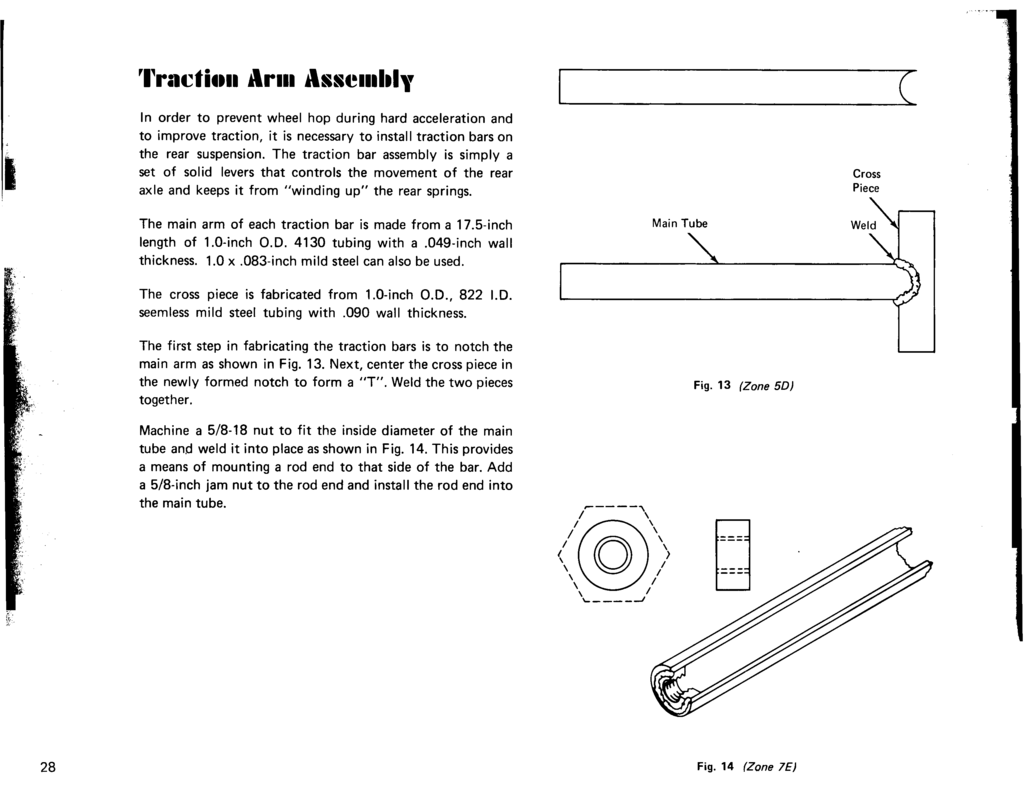
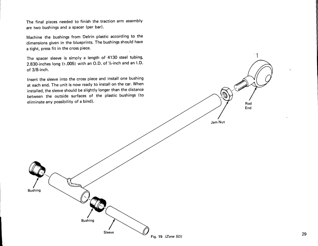
Traction Arm Assembly
Page 28
Page 29
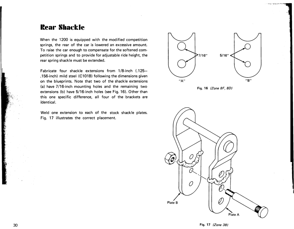
Rear Shackle
Page 30
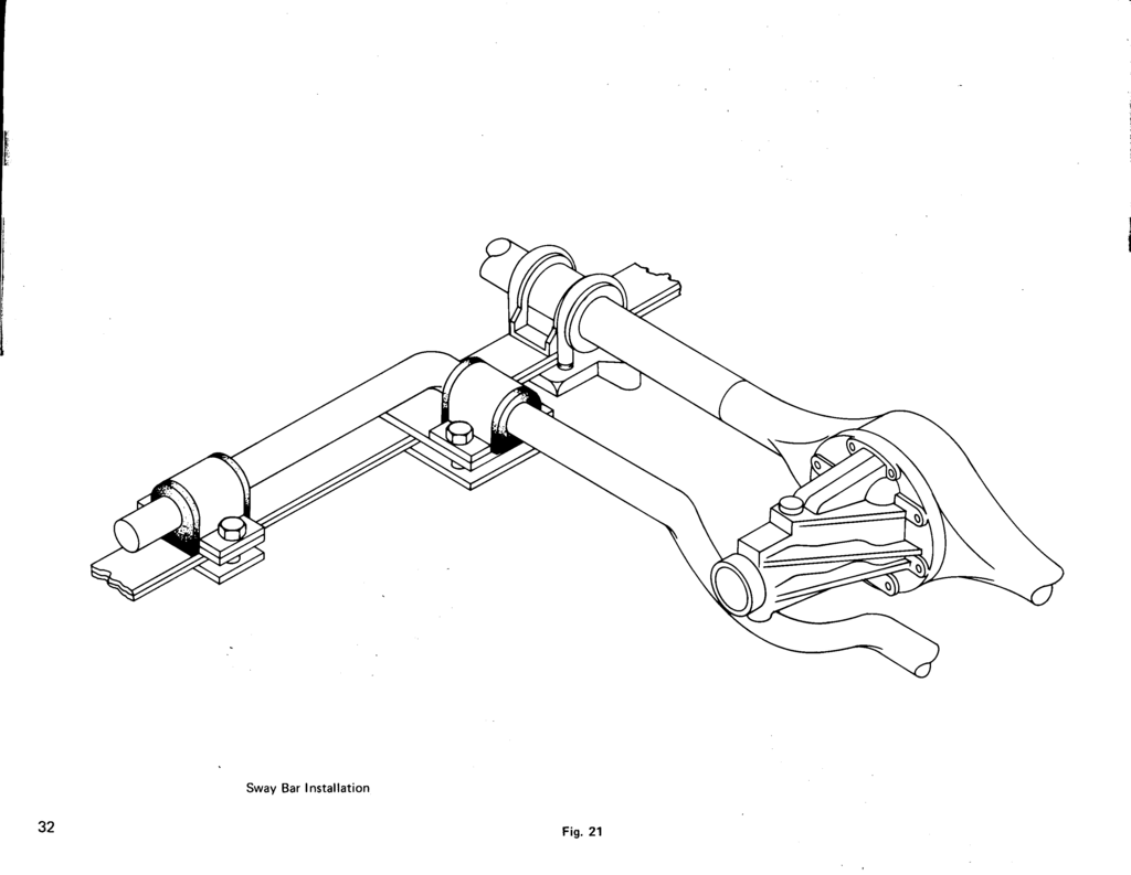
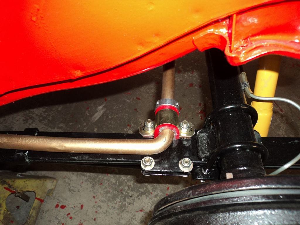
Rear Sway Bar Assembly
Page 31
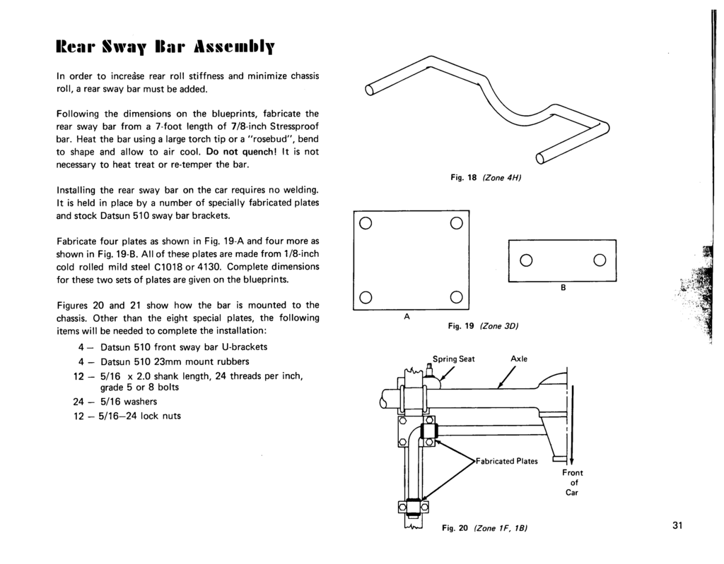
Page 32
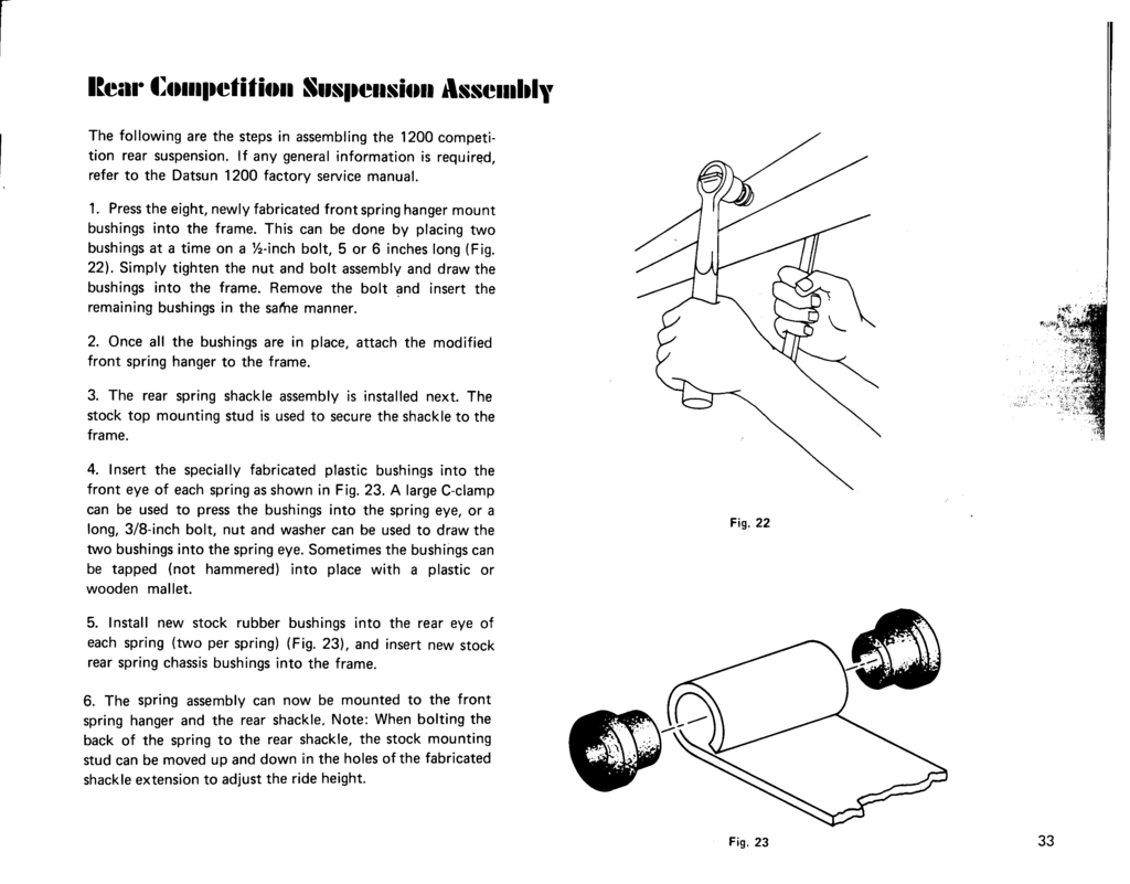
Rear Competition Suspension Assembly
Page 33
Page 34
Page 35
Final Adjustments
Page 36
General Handling
Page 37
Parts Lists
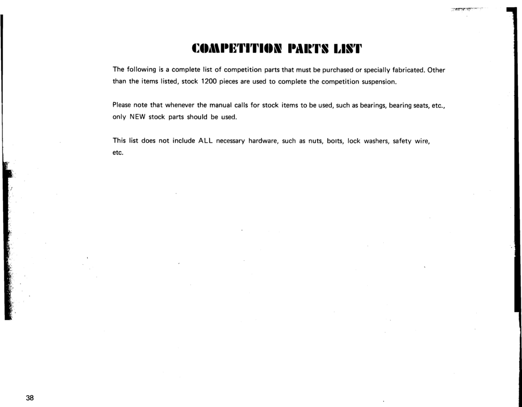
Competition Parts Lists
Page 38
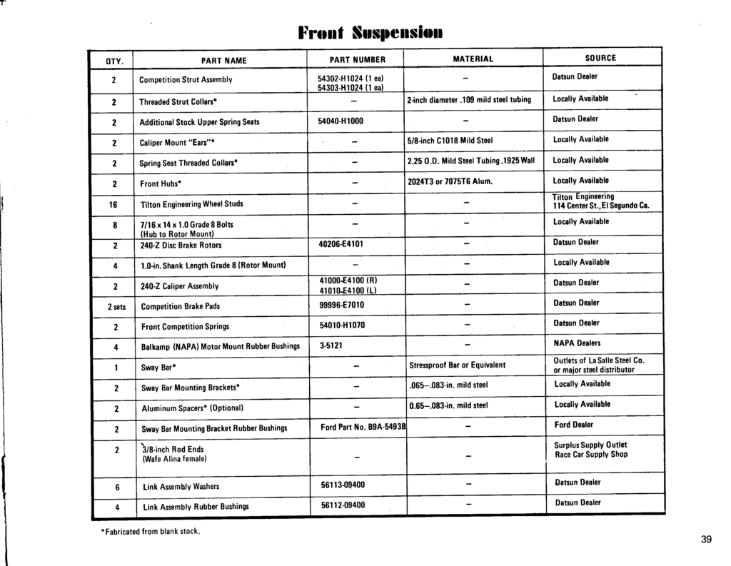
Front Suspension
Page 39
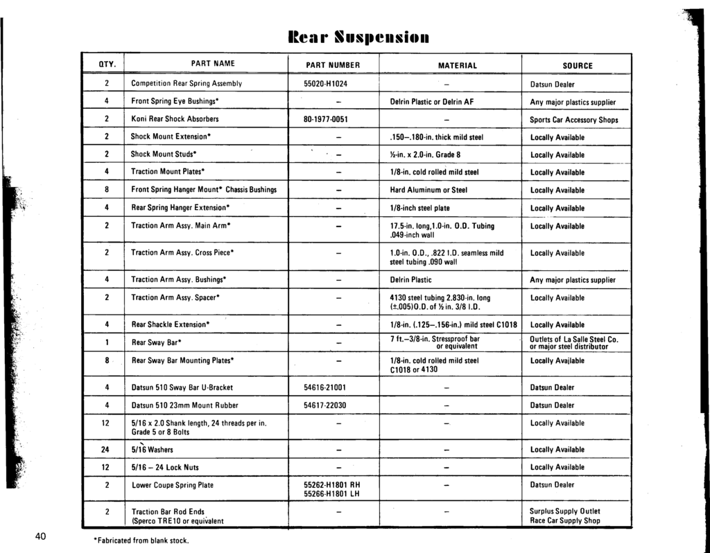
Rear Suspension
Page 40
Back Cover
prepared for
COMPETITION DEPARTMENT
By
TECHNICAL COMMUNICATIONS
TECHNICAL ENGINEERING DEPARTMENT