![[Datsun 1200 encyclopedia]](/wiki/upload/wiki.png)
In 1977 Nissan released the B310 and three months later introduced new trims GX-E and SGX-E.
These featured a fuel injected (EGI) engine — the legendary A14E motor.
These improved upon the B310 GX which came with a single carburetor A14S motor. Nissan "introduction" Service Bulletin Number 350 highlights the features of the new model. In this case the biggest change from the GX to the GX-E is the Fuel Injection system. The Service Bulletin No. 350 is 60 pages.
PART 1 (Overview/Specifications)
PART 2 (Engine)
PART 3 (Chassis, Body)
|
 |
Engine
エンジン Engine
1. 概要 Overview
Page 22 | Page 22 PDF
1. 概 要
1-1 概 要
- ダットサン サニー E-HB310型車に、53年度排出ガス規制適合のA14型EGI仕様エンジン 搭載車を新たに設けました。
- この項では、A14型キャブレーター仕様エンジンとの相違点及び新たに追加された各装置につい て記載いたします。
項目 53年度排出ガス規制適合車
- エンジン A14型 (キャブレーター仕様) E-HB310型車
- エンジン A14型 (EGI仕様) E-HB310型車
- エンジン A12A型 (キャブレーター仕様) E-B310型車
- エンジン A12型 (キャブレーター仕様) ~
項目 50年度排出ガス規請適合車
- エンジン A14型 (キャブレーター仕様) H-VHB310型車
- エンジン A14型 (EGI仕様) E-HB310型車 ~
- エンジン A12A型 (キャブレーター仕様) ~
- エンジン A12型 (キャブレーター仕様) H-VB310型車
エンジン本体
- 電子制御燃料噴射装置の採用に伴い、キャブレーター仕様に対しマニホールド関係を変更しま した。
電子制御燃料噴射装置
- 電子制御燃料噴射装置をエンジンに併せて新設しました。従来のB-PA10 (L16エンジン)、 B-S11(L18型エンジン)型車との主な違いは、コールドスタート パルプなど低温始動時の 部品を廃止し、全てコントロールユニットで制御し、フューエルインジェクターから噴射さ せるようにするとともに、コントロールユニットには車速などにより空燃比を切り替える 回路も組み込みました。
排気ガス還流(EGR)装置
- キャブレーター仕様と同様負荷比例式を採用し、大量排気ガス流(EGR)をするとともに、 運転状態に応じて、遠流率(量)を制御する制御装置を採用しました。
1. Overview
1-1 Overview
- The Datsun Sunny E-HB310 model is now equipped with an A14 EGI specification engine that complies with the 1953 exhaust gas regulations.
- This section describes the differences from the A14 type carburetor specification engine and the newly added devices.
Item: Vehicles compliant with 1978 exhaust gas regulations
- Engine A14 type (carburetor specification) E-HB310 type car
- Engine A14 type (EGI specification) E-HB310 type car
- Engine A12A type (carburetor specification) E-B310 type car
- Engine A12 type (carburetor specification) ~
Item: Vehicles compliant with 1975 exhaust gas regulations
- Engine A14 type (carburetor specification) H-VHB310 type vehicle
- Engine A14 type (EGI specification) E-HB310 type car ~
- Engine A12A type (carburetor specification) ~
- Engine A12 type (carburetor specification) H-VB310 type car
ENGINE BODY
- Due to the adoption of an electronically controlled fuel injection system, the manifold relationship has been changed compared to the carburetor specification.
Electronically controlled fuel injection device
- An electronically controlled fuel injection system was newly installed along with the engine. The main difference from the conventional B-PA10 (L16 engine) and B-S11 (L18 engine) models is that cold start parts such as cold start pulp are eliminated, and everything is controlled by the control unit, and the fuel injector In addition to injecting fuel, the control unit also incorporates a circuit that switches the air-fuel ratio depending on vehicle speed and other factors.
Exhaust gas recirculation (EGR) device
- Similar to the carburetor specification, a load proportional system is used to control large exhaust gas flow (EGR), and a control device is used to control the remote flow rate (amount) according to the operating conditions.
Page 23 | Page 23 PDF
二次空気供給装置
- 二次空気導入(EAI) 装置をキャブレーター仕様と同様採用しました。なおEAIバルブは1 個です。
エンジン電装
- ディストリビューターのバキューム進角は、アイドル時にもマニホールド負圧を利用して進角 させ、燃料経済性、運転性の向上を図りました。
- また、オルタネーターは、信頼性の高いICレギュレーター付きオルタネーターを採用しまし
排気系、冷却系、燃料系
- キャブレーター仕様とほぼ同じです。
1-2 エンジン番号打刻
- EGI社エンジンの実施始番号は次のとおりです。
- エンジン実施始番号
- E-HB310 A14-121716P~
SECONDARY AIR SUPPLY DEVICE
- A secondary air introduction (EAI) device is used in the same way as the carburetor version. Please note that there is only one EAI valve.
ENGINE ELECTRICAL EQUIPMENT
- The vacuum advance angle of the distributor uses manifold negative pressure to advance even when the engine is idling, improving fuel economy and drivability.
- Also, the alternator uses a highly reliable IC regulator.
EXHAUST SYSTEM, COOLING SYSTEM, FUEL SYSTEM
- Almost the same as the carburetor specifications.
1-2 ENGINE NUMBER STAMPING
- The starting numbers for EGI engines are as follows.
- Engine starting number
- E-HB310 A14-121716P~
Page 24 | Page 24 PDF
1.4 NAPS specification
Page 25 | Page 25 PDF
Engine Room
1.5 エンジン ルーム Engine Room
Page 26 | Page 26 PDF

Engine Appearance
1.6 エンジン外観 Engine Appearance
Page 27 | Page 27 PDF

Left side of engine

Japanese
Right side of engine

Japanese
EGI Control System
1.7 A-series EGI-specification engine Control System
Page 28 | Page 29 PDF
Engine Main Parts Comparison Table
1.8 エンジン主要部品対照表 Engine Main Parts Comparison Table
Page 29 original Page 30 PDF
1-8 エンジン主要部品対照表
本はA14EGI仕様エンジンのA14型キャブレーター仕様エンジンに対して部品の異なる ものを記載しました。ただし、キャブレーター仕様特有の部品については除いてあります。した かって本表にないものは、A11型キャブレーター仕様エンジンと共通部品を示します。
表の見方: E-B310型車(A12A型キャブレーター仕様エンジン)をAとしたとき、E-HB310型
Page 30 original Page 31 PDF

Basic Engine
2. エンジン本体 Basic Engine
Page 31 original Page 32 PDF


Intake Manifold Stud Length
1  45mm length
2  40mm length
   28mm length (additional studs)
水穴 water holes
Piston
2.2 Piston
No. 1-4 "E"
Camshaft
Cam taken from B-HB211 (A14 Twin Carburetor)
Timing
A14E: 20, 56, 58, 18
A14:  14, 54, 56, 20
Valve Spring and Valve Seat
Page 32 original Page 33 PDF

Same as B-HB211 (A14 Twin Carburetor)
Rocker Cover Assembly
2.5
A14E: Gold Top
A14S: Blue Top

Japanese
キャブレーターエンジン仕様 Carburetor specification
EGI仕様 EGI specification
Blowby Hose ASSY
2.6 PCV Positive Crankcase Ventilation System

Manifold
2.2 Manifold
Intake Manifold
2.2.1
Page 33 original Page 34 PDF


Japanese
負圧取り出し Negative pressure taken out
VVT バルブへ To the VVT Valve
Exhaust Manifold
2.2.2
Carburetor specification and ???
Compatibility: None
キャブレーター仕様との?いは、ニ?空気?入バルブが1?のめ、リヤ側のEAIチュープ?リ付け穴を?止しました。
互換性:なし
Manifold Cover
2.2.3
Intake Manifold Gasket
2.2.4

Japanese
取り付け面 clamp face
See 14035-H9202
Intake Manifold Bracket
2.2.5
Electronic Fuel Injection
3.
電子制御燃料噴射装置(ニッサンEGI)
Electronic Control Fuel Injection (Nissan EGI)
Page 34 original Page 35 PDF
電子制御燃料噴射装置(ニッサンEGI)は、すでにB-PA10(L16型エンジン)びB-S11(L18型エンジン)型車デ案内してあるものとほぼ同じです。コールド スタート バルブ増量をクランキング増量に仕様変夏し、また空燃比切替装置を追加しました。
ここでは従来のもの(L16型、L18型エンジン用)と比較し記載します。互換性は1-8 エンジン主要部品対照表を参照願います。
The electronically controlled fuel injection system (Nissan EGI) is almost the same as that already introduced for B-PA10 (L16 type engine) and B-S11 (L18 type engine) type vehicles. Cold start valve increase was changed to cranking increase, and an air-fuel ratio switching device was added.
Here, it is compared with the conventional one (for L16 type and L18 type engines). For compatibility, refer to 1-8 Engine main parts comparison table.
B-PA10 (L16 engine) [ A10 Stanza]
B-S11  (L18 engine) [ S10 Silvia]
B = Japan_Emissions#B
Fuel System
3-1
燃料系
Fuel System
Fuel Pump, Fuel Damper
3.1.1 Fuel Pump, Fuel Damper
(1)
フューエル プンプ、フューエル ダンパー
Fuel Pump, Fuel Damper
...
Fuel Filter
3.1.2 Fuel Filter
(2)
フューエル フィルター
Fuel Filter
...
Fuel Tube
3.1.3 Fuel Tube
フューエル チューブ
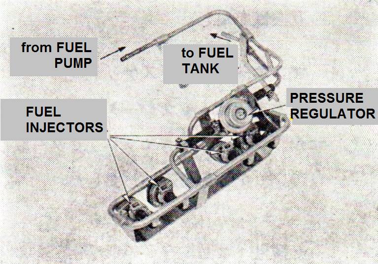
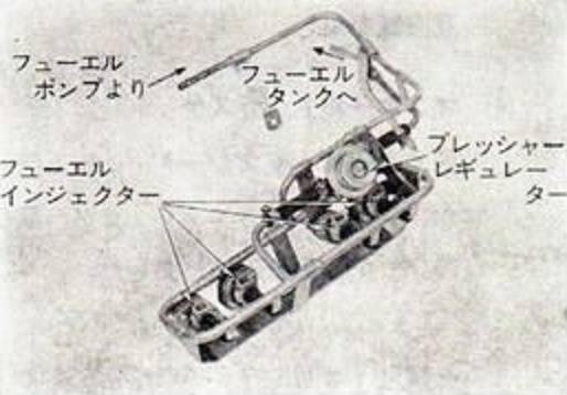
ー体型のフューエル チューブを新設しました。インテーク マニホードとシリンダー ハッドに固定され、 フューエルインジェクターとプレッシャー レギュレーターが取リ付けさられます。
FUEL TUBE
-A new type of fuel tube has been established. The intake manifold and cylinder are fixed to the fuel, and the fuel injector and pressure regulator are attached.
Fuel Injector
3.1.4 Fuel Injector
(4)
フューエル インジェクター
Fuel Injectors
...
Pressure Regulator
3.1.5 Pressure Regulator
プレッシャー レギュレーター
燃圧をー定にする作重は従来と同じですが、フューエル チューブの体化により形状を変
PRESSURE REGULATOR
Although the weight of the fuel pressure is constant, it is the same as before, but the shape is changed by the fuel tube.
Air System
3.2 空気系
Air System
Page 35 original Page 36 PDF
Air Duct
3.2.1 エア導入ダクト
Air Inlet Duct
車両形状に合せて新設しました。
Newly established according to the vehicle shape.
Air Cleaner Element
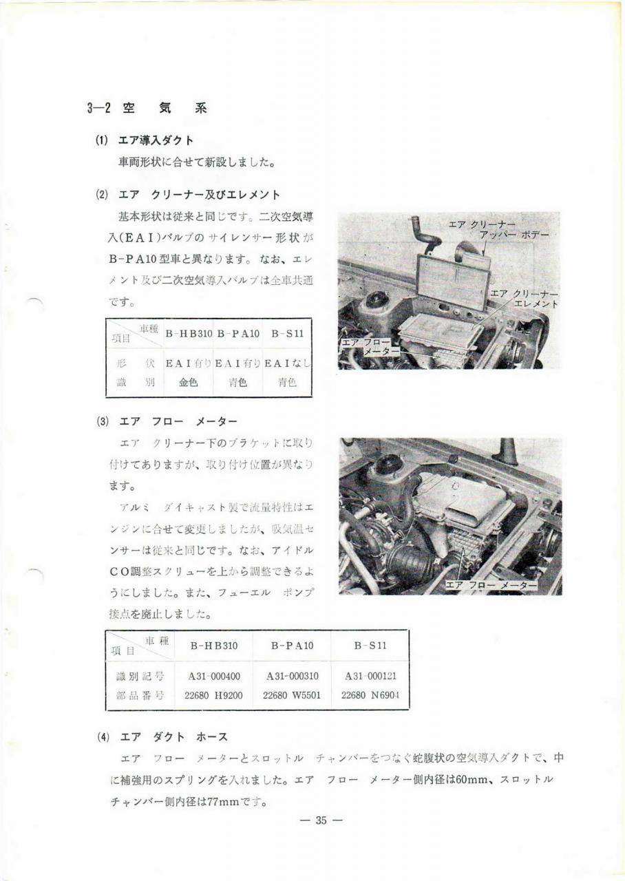
3.2.2 エア クリーナー及びエレメント
Air Cleaner and Element
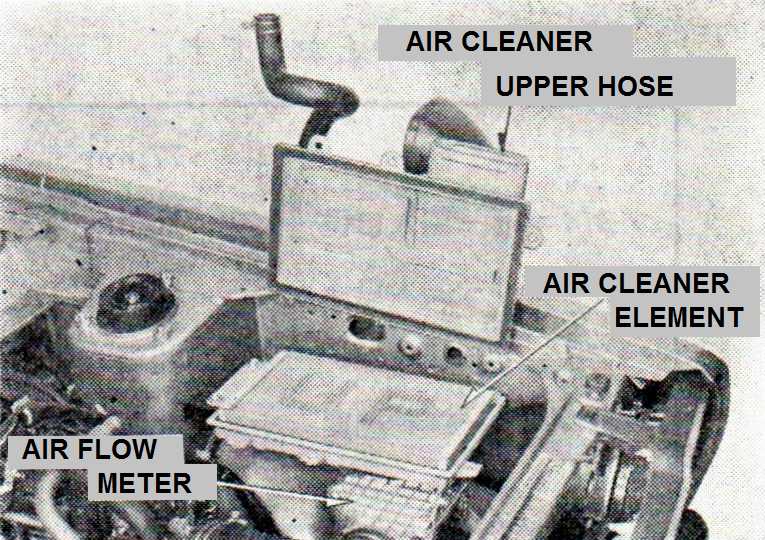
車両形状は従来と同じです。二次空気導入(EAI)バルブのサイレンサー形状がB-PA10型車と異なります。なお、エレメント及び二次空気導入バルブは全車共通です。
The vehicle shape is the same as before. The silencer shape of the secondary air introduction (EAI) valve is different from the B-PA10 type car. The element and secondary air introduction valve are common to all models.
車種 car model   B-HB310  B-PA10  B-S11
                Sunny     Stanza   Silvia
項目 item
形状 form        EAI 有り  EAI 有り  EAI 有り
識別             金色      青色     青色
Identification  gold     blue    blue
Air Flow Meter
3.2.3 エア フロー メーター
Air flow meter
...
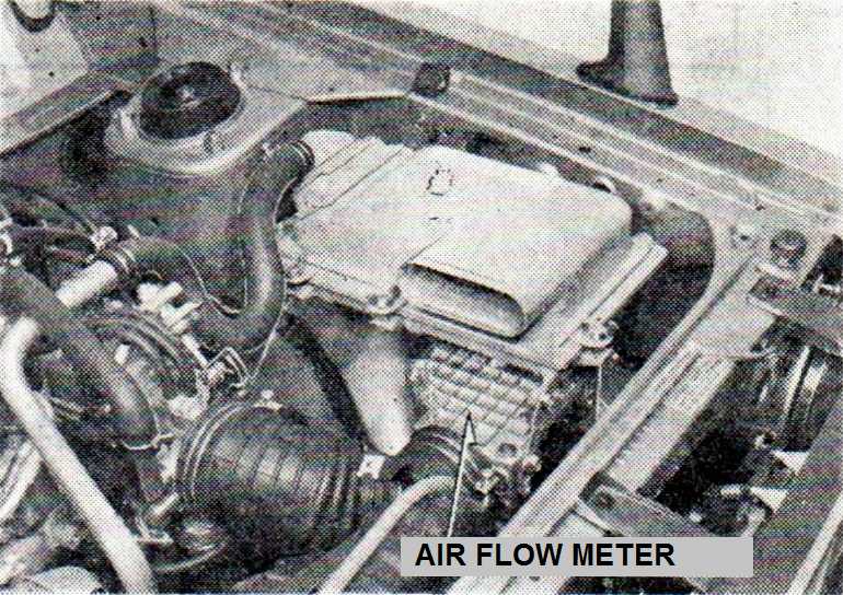
車種 car model B-HB310  B-PA10     B-S11
              Sunny      Stanza      Silvia
項目 item
識別記号 ID   A31-000400  A31-000310  A31-000121
部品番号 PN   22680-H9200 22680-W5501 22680-N6904
Air Duct Hose
3.2.4 エア ダクト ホース
Air duct hose
エア フロー メーターとスロットル チャンバーをつなぐ蛇腹状の空気空導入ダクトで、中に補強用のスプリングを入れました。エア フロー メーター側内径は60mm、スロットル チャンアー側内径は77mmです。
A bellows-shaped air-air introduction duct that connects the air flow meter and the throttle chamber with a spring for reinforcement inside. Air flow meter inner diameter is 60mm, throttle inner diameter is 77mm.
I.D. 60mm air flow meter
I.D. 77mm throttle chamber
Throttle Chamber
3.2.5 Throttle Chamber
Page 36 original Page 37 PDF


Air Regulator port
Blowby Gas (PCV) port
Idle port
EGR port
VVT port
Distributor Vacuum port
Air Regulator
3.2.6 Air Regulator
???
車種 car model
流量 flow rate
識別 identification
項目 item
| B-PA10 | |||
| B-HB310 | B-S11 | ||
| 20°C flow rate | 14m³/h | 19m³/h | |
| identification | A32-000400 | - |
Electronic Control System
3.3 電子制御系
Page 37 original Page 38 PDF

Control Unit
3.3.1 Control Unit
Fuel Increase Correction
3.3.2 燃料増量補正
Page 39 original Page 41 PDF

Air-fuel ratio switching instrumentation
3.4 空燃比切替装
Page 40 original Page 42 PDF


EFI Relays
3.5 電子制御燃料噴射装?のリレー類
Page 41 original Page 43 PDF

3.5.1 EGI Relay
3.5.2 Fuel Pump Relay
EGR
4. 排気 ガス還流(EGR)装置
4. Exhaust Gas Recirculation (EGR) Equipment
Page 42 original Page 44 PDF

EGR Equipment
4-1 排気ガス還流装置の装置;
4-1 EGR Equipment
EGR装置は、キャブレター仕様と同じ負荷比例代です。制御信号として排圧のほかに吸入空気量(負荷)に比するベンチュリー負圧を加する
COMPONENT PARTS
  PART NAME                FUNCTION
1 neutral switch           neutral position detection
2 speed sensor, speed amp  detection vehicle speed from about 45 km/h
3 TV valve                 water temp (about 50C) ???
4 VC solenoid valve        ?
5 VVT valve                ?
6 EGR control valve        ?

Page 43 original Page 45 PDF

WATER TEMP         TRANSMISSION   VEHICLE         VC solenoid  VENTURI
(TV VALVE)         GEAR POSITION  SPEED           valve
about 50C or less  -              -               -
about 50C or more  neutral        -               ON
                   except neutral ~45km/h or less OFF
                                  ~45km/h or more ON
EGR 2
4-2 排気ガス還流装置の概要
4-2 Overview of the Exhaust Gas Recirculation system
EGR Control Valve
4.2.1 EGR Control Valve

VVT Tube
4.2.2 VVT Tube
VVT Valve Bracket
4.2.3 VVT Valve Bracket
Page 44 original Page 46 PDF


取り付け mounting
EGR Passage
4.2.4 EGR Passage

排気ガス涌 路
Straight Connector
4.2.5 Straight Connector
互換性:なし(A12A型、キャブレター仕様と有)
Compatibility: None (A12A type, carburetor specifications and ?)
EGR Tube
4.2.6

水温 water temperature
TV = Thermal Valve
Vacuum Piping Figure
4-3 バキューム配管実態図
4-3 Vacuum Piping Figure
Page 45 original Page 47 PDF


長さ length
識別色 identification color
緑 green
白 white
青 blue
黄 yellow
桃 peach
部位 part
No 長さ    識別色   部位
 1 170mm (green)  vacuum gallery - pressure regulator
 2  90mm (peach)  VVT tube - VVT valve
 3 200mm (white)  VVT valve - TV valve side 3-way connector
 4  70mm (yellow) vacuum gallery - distributor side 3-way connector
 5  50mm (yellow) vacuum gallery - distributor side 3-way connector
 6 190mm (white)  vacuum gallery - TV valve
 7 170mm (white)  EGR control valve - TV valve side 3-way connector
 8 110mm (white)  TV valve - 3-way connector
 9 540mm (yellow) distributor - 3-way connector
10 120mm (blue)   vacuum gallery - VC solenoid valve [Vacuum Cut]
11 200mm (blue)   VVT valve - VC solenoid valve
12 200mm (blue)   throttle chamber - vacuum gallery
13  90mm (green)  vacuum connector - vacuum gallery
14 130mm (yellow) throttle chamber - vacuum gallery (distributor use)
15 230mm (blue)   throttle chamber - VC solenoid valve
16 170mm (white)  throttle chamber - vacuum gallery (EGR control valve use)
17 blanking cap
Air Cleaner and EAI
5. エア クリナー及び二次空気導入(EAI)装置 Air Cleaner and Exhaust Air Induction (EAI) Equipment
Page 46 original Page 48 PDF

left caption: 接続ホース Connecting Hose
right caption: EAI バルブ Valve

Japanese
lower caption: 二次空気導入チューブ Secondary air induction tube
EAI Hose
5.1
EAI Valve
5.2
Page 47 original Page 49 PDF

EAI Tube
5.3
Engine Electrical
6. Engine 電装 Electrical
Page 48 | Page 51 PDF
Distributor
6.1 Distributor [points type]
Hitachi D4A7-01
Mitsubishi T4T00475
Centrifugal Advance 12 degrees maximum @ 2400 rpm:

Vacuum Advance 13.5 degrees maximum:

Alternator
6.2 Alternator
IC internally regulated
Hitachi LR150-36
Mitsubishi AQ2250C31
PA10 EGI [Datsun Stanza]

Fuel System
7. 燃料系統 Fuel System
page 49 | page 52 PDF
燃料系 Fuel System
基本的には、キャブレーター仕様とはぼ同じですが、燃ホースの径がー部異なります。Basically, it is the same to pot and carburetor specifications - diameter of the fuel hose differs.
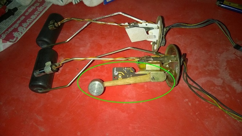
仕様 Specification
...
フューエル ゲージ  ユニット Fuel Gauge Unit
サーミスター式(GL以上)
Carburetor: Thermistor type (GL or more)  EGI: Thermistor type
...
フューエル チューブ Fuel Tube
  アウトレット       Outlet  6.35mm carburetor  12mm EGI
  リターン          Return  6.35mm carburetor   8mm EGI
Regular vs GL/EGI sender
8. ????
Exhaust System
[page 49 original, page 52 PDF]
8. 排気系統 Exhaust System
排気系 Fuel System
排気系は、触媒コンバータ(サイズ、容量)、... Exhaust system, catalytic converter (size, capacity), ...