![[Datsun 1200 encyclopedia]](/wiki/upload/wiki.png)
In 1977 Nissan released the B310 and three months later introduced new trims GX-E and SGX-E.
These featured a fuel injected (EGI) engine — the legendary A14E motor.
These improved upon the B310 GX which came with a single carburetor A14S motor. Nissan "introduction" Service Bulletin Number 350 highlights the features of the new model. In this case the biggest change from the GX to the GX-E is the Fuel Injection system. The Service Bulletin No. 350 is 60 pages.
PART 1 (Overview/Specifications)
PART 2 (Engine)
PART 3 (Chassis, Body)
|
 |
Contents |
Chassis
Propeller Shaft
Page 50 概要 Summary (PDF page 53)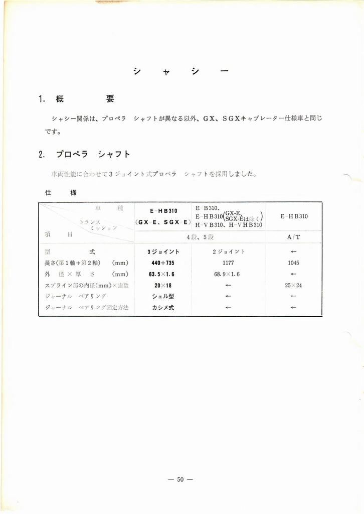
1.概 要
シャシー関係は、プロペラ シャフトが異なる以外、GX、SGXキャブレーター仕様車と同同じです。
Chassis relationship of SGX to GX carburetor-specification car is the same, except that the propeller shaft is different.
2. プロペラ シャフト
車両性能に合わせて3ジョイント式プロペラ シャフトをだ採用しました。
3-joint propeller shaft adopted per vehicle performance
Model                      E-B310,
                           E-HB310(exc.GX-E,SGX-E)
             E-HB310       H-VB310,
             (GX-E/SGX-E)  H-VHB310   E-HB310
Trans.       -- 4speed, 5speed --     A/T
Type         3-joint       2-joint    <--
Length       440+735 mm    1177 mm    1045 mm
O.D.         63.5 mm       68.9 mm    <--
Thickness    1.6 mm        <--        <--
Spline I.D.  20x18         <--        25x24
Journal      shell type    <--        <--
Fix method   crimped       <--        <--
1. Summary
Chassis relationship of SGX to GX carburetor-specification car is the same, except that the propeller shaft is different.
2. Propeller Shaft
3-joint propeller shaft adopted per vehicle performance
Model                      E-B310,
                           E-HB310(exc.GX-E,SGX-E)
             E-HB310       H-VB310,
             (GX-E/SGX-E)  H-VHB310   E-HB310
Trans.       -- 4speed, 5speed --     A/T
Type         3-joint       2-joint    <--
Length       440+735 mm    1177 mm    1045 mm
O.D.         63.5 mm       68.9 mm    <--
Thickness    1.6 mm        <--        <--
Spline I.D.  20x18         <--        25x24
Journal      shell type    <--        <--
Fix method   crimped       <--        <--
Body
Page 51 ボヂ- Body (PDF page 54)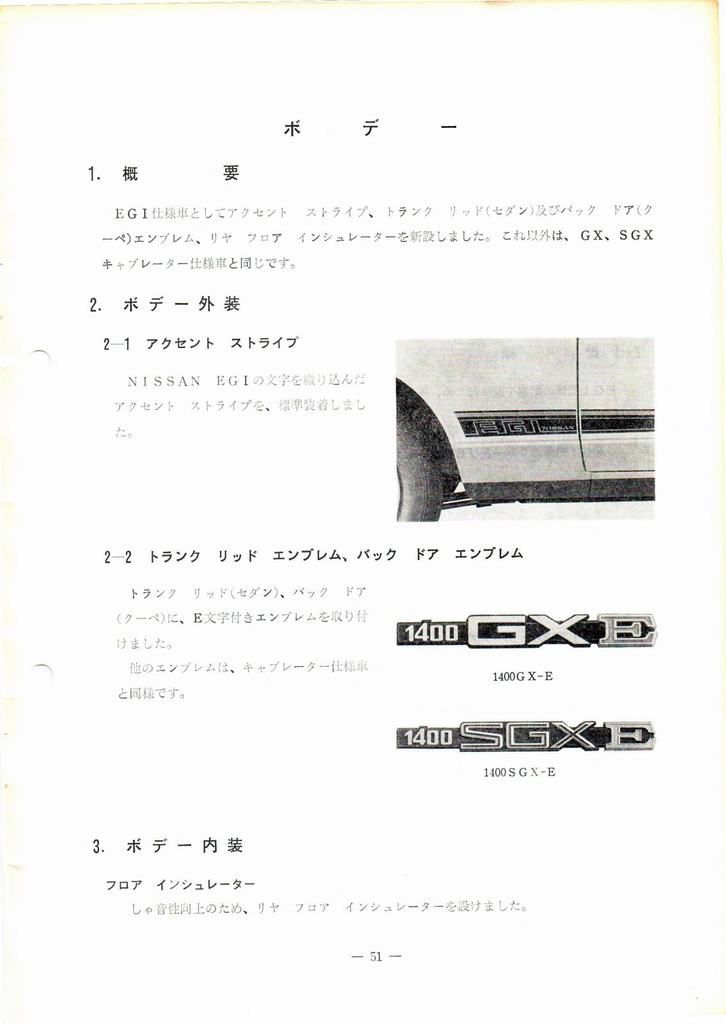
1. 概 要
EGI仕様車としてアクセント ストライプ、トランク リッド(セダン)及びバック ドア(クーペ)エンブレム、リヤ フロア インシュレーターを新設しました。これ以外は、GX、SGX キャブレーター仕様車と同じです。
2. ボ ヂ - 外 装
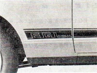
2一1 アクセント ストライプ
NISSAN EGIの文字を織り込んだアクセント ストライプを、標準装着しますた。
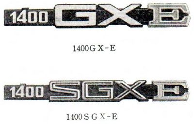
2一2 トランク リット エンブレム、バック ドア エンブレム
トランク リッド(セダン)、バック ドア (クーペ)に、E文字付きエンブレムを取り付けました。 他のエンブレムは、キャブレーター仗様車と同様です。
3. ボ ヂ - 内 装
フロア インシュレーター
しゃ音性向上のため、リア フロア インシュレーターを設けました。
1. Summary
For the EGI-specification car, we have established an Accent Stripe, Emblems for the trunk lid (sedan) and the back door (coupe), and a new rear floor insulator. Otherwise, SGX is the same as GX carburetor-specification car.
2. Body - Exterior
2-1 Accent Stripe
The accent stripes of NISSAN EGI will be standard fitment.
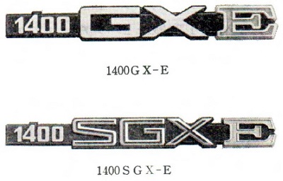
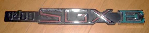
2-2 Trunk Lid Emblem, Back Door Emblem
'E' Emblem for Trunk lid (sedan) & back door (coupe). Other emblems are similar to the carburetor-spec car.
3. Body - Interior
Floor Insulator
For car sound improvement, we provided a rear floor insulator.
Accent Stripe
The accent stripe is interwoven with characters of NISSAN EGI, fitted as standard.
Rear Emblem
2.2 '1400 GX E' or '1400 SGX E' emblem
Body Electrical
Page 52 ボヂ-電装 Body Electrical (PDF page 55)
1. 概 要
ハーネス関係、タコメーター、リレー、ウオッシャータンク、エアコンの高圧ホース及びバキ ューム ホースの取り付け状態以外は、GX、SGXキャブレーター仕様車と同じです。
2. 配線及びリレー
2-1 配 線
EGI関係の配線を設けたため、キャブレーター仕様車とは下記のハーネスが異なります。
メーン ハーネス
EGI関係のリレー及びEGIハーネスとのコネクター、配線を設けました。
ボデー ハーネス
フューエルポンプの配線を設けました。
バッテリー ケーブル
EGI系統のヒュージブル リンクするコネクターを設けました。
ヒュージブル リンク
EGI系統のヒュージブル リンク 0.5 (緑)を、2本設けました。
1. Overview
Other than the installation of the harness, tachometer, relay, washer tank, air conditioner high pressure hose, and vacuum hose, it is the same as the GX and SGX carburetor specification vehicles.
2. Wiring and relays
2-1 Wiring
Because EGI-related wiring has been installed, the following harness is different from the carburetor specification vehicle.
Main Harness
We have provided connectors and wiring for EGI-related relays and EGI harnesses.
Body Harness
We have installed the wiring for the fuel pump.
Battery Cable
We have provided a connector for the fusible link of the EGI system.
Fusible Link
Two EGI system fusible links 0.5 (green) have been installed.
Relays
Page 53 リレー Relays (PDF page 56)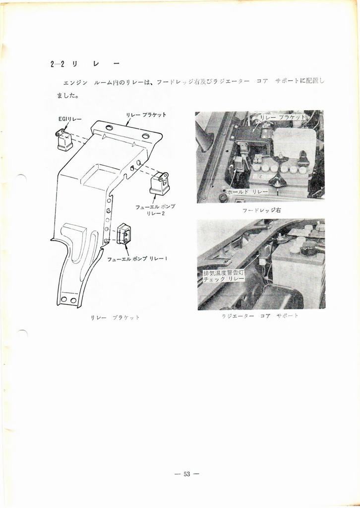
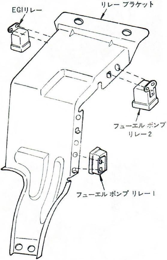
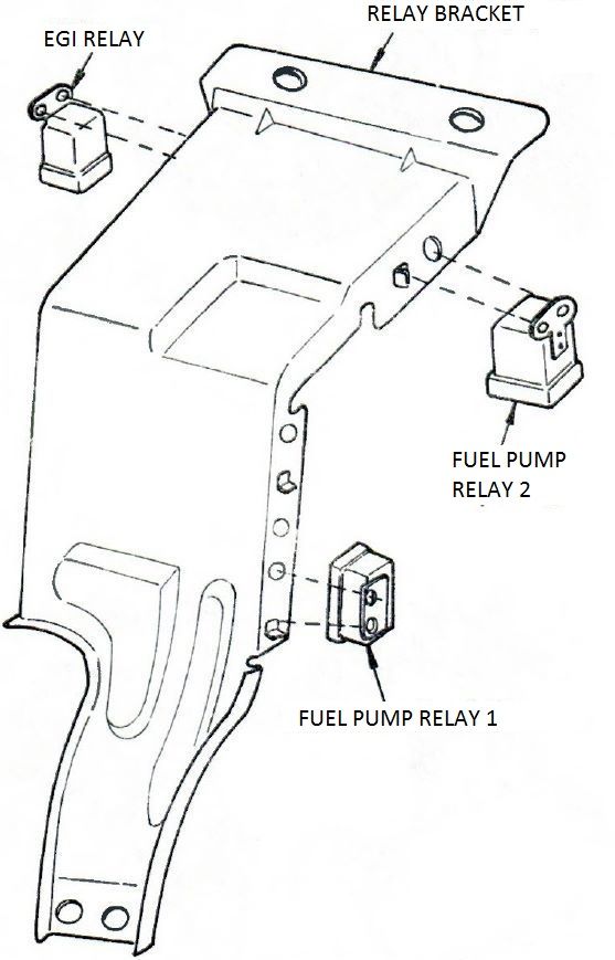
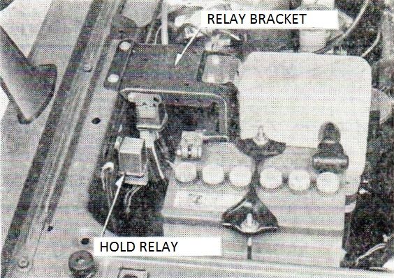
エンジン ルーム内リレー内は、フードレッジ右及びラジエーター コア サポートに配置しました。
リレー ブラッケト
EGI リレー
フューエル ポンプ リレー 2
フューエル ポンプ リレー 1
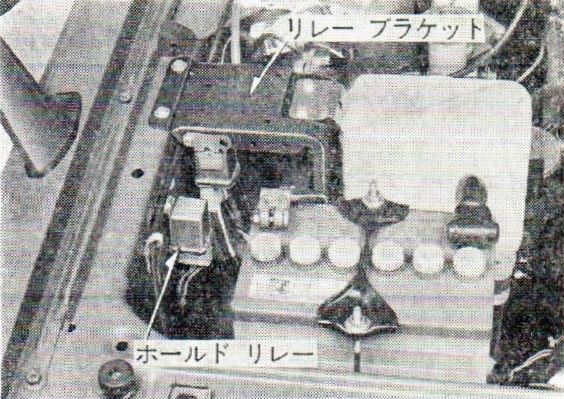
フード レッジ 右
リレー ブラケット
ホールド リレー
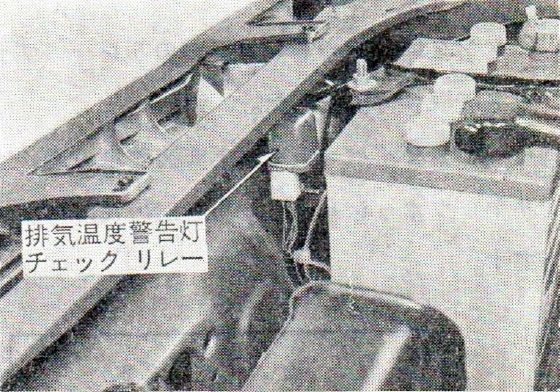
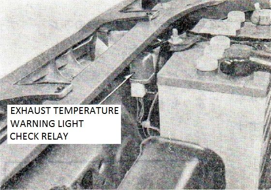
ラジエータ コア サポート
排気温度警告灯 チェック リレー
In the relay engine room, the relays were placed in the hood ledge right and radiator core support.
Relay Bracket
EGI Relay
Fuel Pump Relay 2
Fuel Pump Relay 1
Right Hood Ledge
Relay Bracket
Hold Relay
Radiator Core Support
Exhaust Temperature warning light Check Relay
Tachometer
NOTE: EGI Tachometer has a yellow zone of 6400-6800, compared to 6000-6250 for A14S carbureted engine
Page 54 (upper half) タコメーター Tachometer (PDF page 57)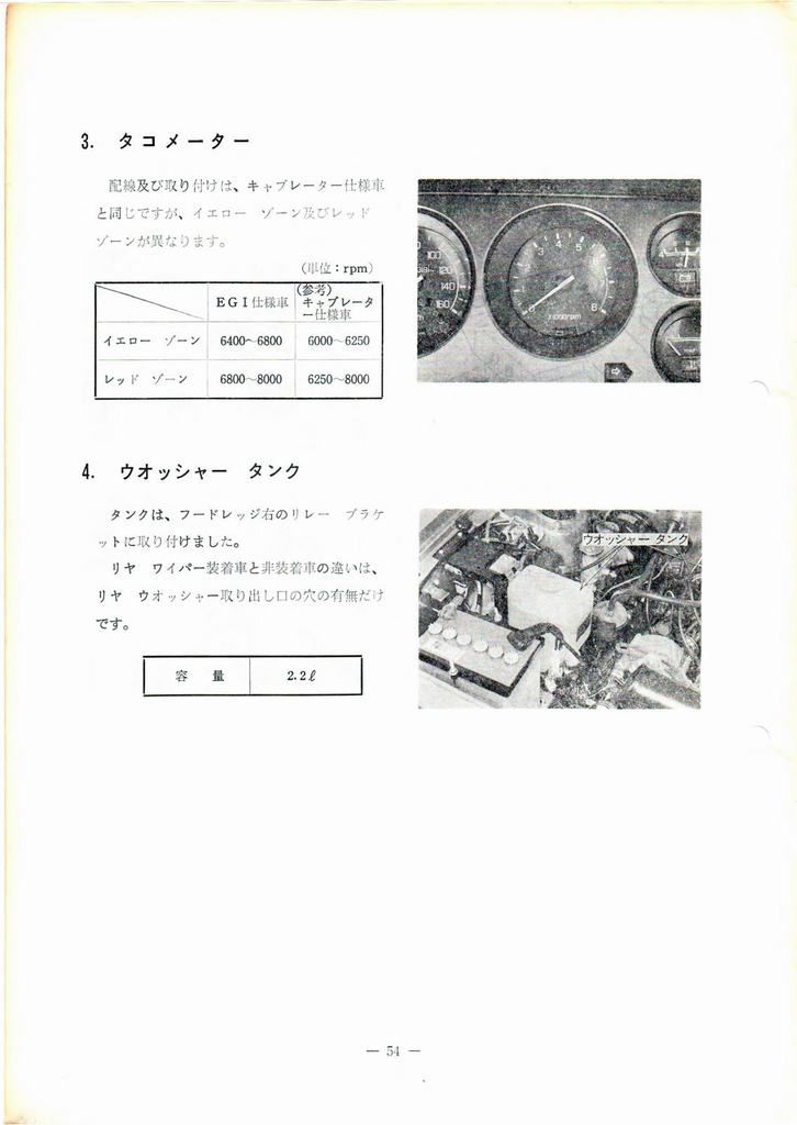
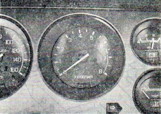
配線及び取り付けは、キャブレーター仕様車と同じですが、イエロー ゾーン及びレッドゾーンが異なります。
                          (単位:rpm)
               EGI仕様車  (参考)キャブレター仕様車
イエロー ゾーン  6400~6800  6000~6250
レッド ゾーン    6800~8000  6250~8000
Wiring and installation is the same as the carburetor specification car, but with different yellow zone and red zones.
                           (unit:rpm)
                EGI-spec   Carburetor
                    car      spec car
Yellow Zone     6400-6800  6000-6250
Red Zone        6800-8000  6250-8000
Washer Tank
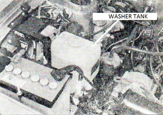
Page 54 (lower half) ウアッシャー タンク Washer Tank (PDF page 57)
タンクは、フードレーッジ右のリレー ブラケットに取り付付けました。
リヤ ワイパー装着車と非装着車の違いは、リヤ ウオッシャー取り出し口の穴の有無だけです。
容 量 2.2 ℓ
ウアッシャー タンク
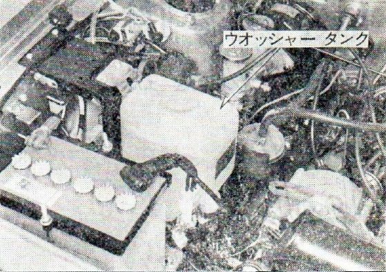
Tank is installed to right hood ledge right on the relay bracket.
Rear wiper-equipped vehicles and non-equipped cars differ only the presence or absence of holes for the rear washer outlet.
Capacity 2.2 ℓ
Washer Tank
Air Conditioner
Page 55 エア コンデイショナー(ヂーラー オプション) Air Conditioner (Cooler Option) (PDF page 58)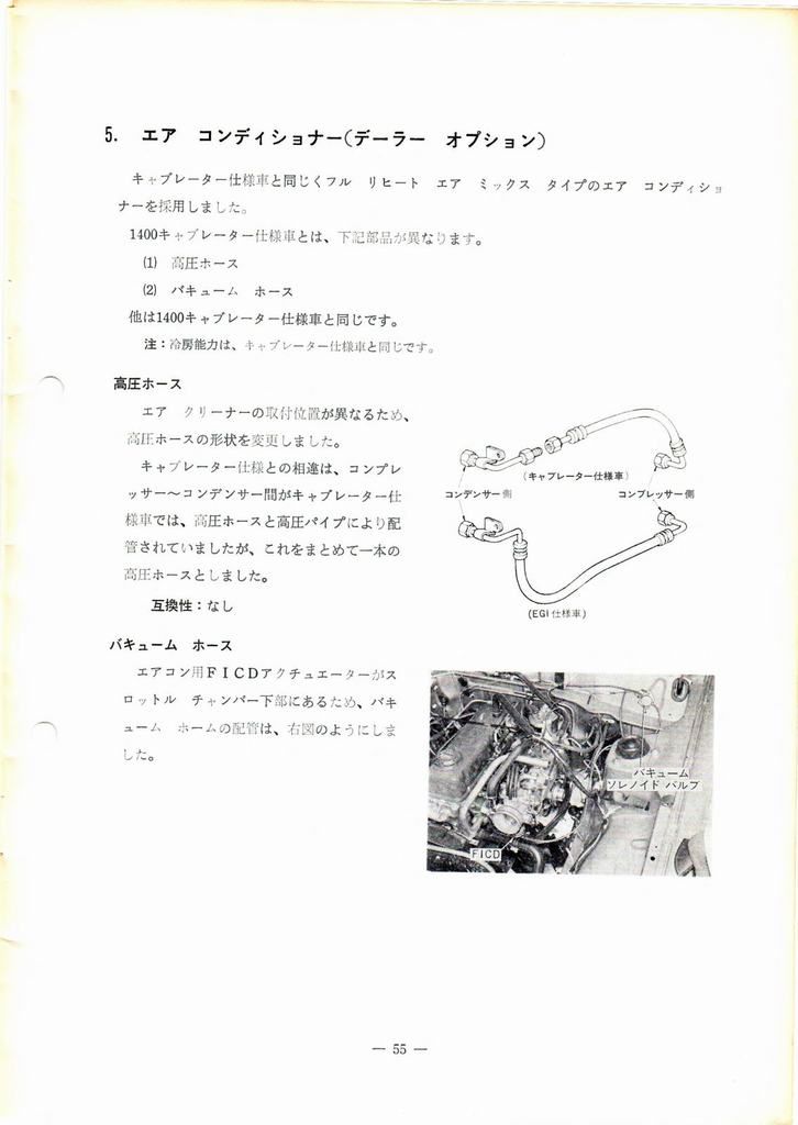
キャブレーター仕様車と同同じく同フル リヒート エア ミックス タイプのエア コンデイショナーを挟用しました。
1400キャブレーター仕様車とは、下記部品が異なります。
(1) 高圧ホース
(2) バキューム ホース
他は1400キャブレーター仕様車同じです。
注:冷房能カは、キャブレーター仕様車と同じです。
Carburetor-specification car and the same also the air conditioner over the same full reheat air mix type I have for today.
For the 1400 carburetor-specification car, the following parts differ.
(1) high-pressure hose
(2) vacuum hose
The other parts are the same as the 1400 carburetor-specification car.
    Note: The cooling ability is the same as
    the carburetor-specification car.
High Pressure Hose
Page 55 (middle third) 高圧ホース High Pressure Hose (PDF page 58)
エアクリーナーの取付位置が異なるため、 高圧ホースの形状を変更しました。
キャブレーター仕様との相違は、コンプレ ッサー~コンデンサー間がキャブレーター仕 前車では、高圧ホースと高圧パイプにより配 皆されていましたが、これをまとめて一本の 高圧ホースとしました。
互換性:なし
コンデンサー コンプレッサー個
(キャブレーター仕様車)
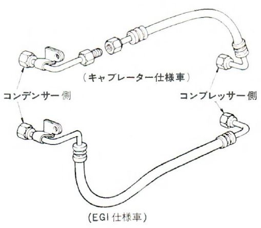 (EGI仕様車)
High Pressure Hose
The shape of the high pressure hose has been changed because the installation position of the air cleaner is different.
The difference with the carburetor specification is that the connection between the compressor and the condenser was connected by a high pressure hose and high pressure pipe in cars with a carburetor, but these have been combined into one high pressure hose.
Compatibility: None
Condensor side Compressor side
(Carburetor specification car)
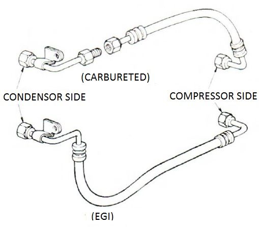 (EGI specification car)
Vacuum Hose
Page 55 (lower third) バキューム ホース Vacuum Hose (PDF page 58)
バキューム ホース
エアコン用FICDアクチュエーカーがスロットル チャンバー下部にあるため、バキューム ホームの配管は、右図のようにしました。
バキューム ソレノイド バルブFICD
Vacuum Hose
FICD actuator for aircon is at the bottom of the throttle chamber, plumbing vacuum home as shown in the diagram on the right.
Vacuum Solenoid ValveFICD
Final Page
Page 56 [Publisher Statement] (PDF page 60)
|
複製を禁ず
印刷発行 昭 和 53 年 2 月
実費 210円
発行所 日産自動車株式会社
担当 サービス部
東京都中央区銀座6ー17ー1
T-802090 |
|
Replication prohibited
Print issued in February 1978
Actual cost 210 yen
Publishing Office Nissan Motor Co., Ltd.
Service Representative Part
Ginza, Chuo-ku, Tokyo 6-17-1
T-802090 |