![[Datsun 1200 encyclopedia]](/wiki/upload/wiki.png)
| Revision as of 07:28, 20 November 2016 ddgonzal (Talk | contribs) (->Lamps) <- Previous diff |
Current revision ddgonzal (Talk | contribs) (->B210) |
||
| Line 1: | Line 1: | ||
| - | The lighting circuits generally use Green wires. Newer 1200 utes differ. The following information is for USA-spec models. Other countries vary slight, see the appropriate [[Wiring Diagram]]. | + | The lighting circuits generally use Green wires. Newer 1200 utes differ. The following information is for USA-spec models. Other countries vary slight, see the appropriate [[Wiring Diagram]] or click Edit and add the information here. |
| - | Also see [[Headlight Wiring]] | + | {{See|Headlight Wiring}}<br> |
| + | |||
| + | = Wire color codes = | ||
| + | {{wire_colors}} | ||
| = Overview = | = Overview = | ||
| - | The lighting circuits generally use Green wires. | + | The lighting circuits generally use Green wires: |
| * G - IG-hot from Fuse Box | * G - IG-hot from Fuse Box | ||
| * GY - Brake lights (stop lamps) | * GY - Brake lights (stop lamps) | ||
| - | * GL - running lights (parking lights) | + | * GL or GW - running lights (parking lights) |
| * GB - R.H. Turn Signal + running lights | * GB - R.H. Turn Signal + running lights | ||
| * GR - L.H. Turn Signal + running lights | * GR - L.H. Turn Signal + running lights | ||
| - | [http://datsun1200.com/modules/myalbum/photo.php?lid=19666 http://datsun1200.com/uploads/photos/19666.jpg] | + | |
| + | [[Lighting Switch]] and [[Turn signal switch]] circuits | ||
| + | <br>{{Album|19666}} | ||
| = Dash Lamps = | = Dash Lamps = | ||
| Line 22: | Line 27: | ||
| * Oil pressure indicator lamp | * Oil pressure indicator lamp | ||
| - | = Hazards = | + | = Hazards Wiring = |
| - | The 4-way '''hazard''' lights are part of the Turn Signal circuit. See next section. The hazards were OPTIONAL in Australia. | + | The 4-way '''[[Hazards]]''' lights are part of the Turn Signal circuit. See [[#Turn Signals|#next section]]. |
| - | Late Sunny Truck & late USA - single position switch | + | = Park/Tail Circuit = |
| - | <br>[http://datsun1200.com/modules/myalbum/photo.php?lid=2136 http://datsun1200.com/uploads/photos/2136.jpg] | + | When the [[Lighting Switch]] is pulled out one or two stops, these light up: |
| + | * [[#Front Combo Lamp]] "Park" bulbs | ||
| + | * [[#Rear Combo Lamp]] "tail" bulbs | ||
| + | * [[#License Plate Lamp(s)]] | ||
| + | * [[#Dash Lamps|#Dash illumination lamps]] | ||
| + | * [[#Side_Marker_lamp_connector|#side marker lamps]] (North America only) | ||
| - | 3-button switch (parking & hazard) | + | Power comes from the PT fuse in the [[Fuse Box]], and is supplied to the main Green/Blue wire via the [[Lighting Switch]]. |
| - | <br>[http://datsun1200.com/modules/myalbum/photo.php?lid=19647 http://datsun1200.com/uploads/photos/19647.jpg] | + | |
| - | == 1400 == | + | {{Album|27143}} |
| - | [[PB110]] hazard/parking lights switch | + | |
| - | 25880-H2500 SWITCH COMP-hazard & parking | + | |
| - | [http://datsun1200.com/modules/myalbum/photo.php?lid=25557 http://datsun1200.com/uploads/photos/25557.jpg] | + | |
| - | + | ||
| - | パーキングスイッチ | + | |
| - | + | ||
| - | Also see [[Instruments_and_Controls#Hazard_Warning_Switch]] | + | |
| = Turn Signals = | = Turn Signals = | ||
| - | Also see [[Turn Signals]] (include Hazards) | + | Also see: |
| + | * [[Turn Signals]] (include Hazards) | ||
| + | * [[Flasher]] unit | ||
| + | * [[Turn signal switch]] | ||
| - | The T/S path is as follows: From the IG side of the Fuse Box through the 10A "M" terminal (G wire) to the Four-Way Flasher Switch (Hazard Switch). | + | The T/S path is as follows: |
| + | * 12 volts is provided From the IG side of the [[Fuse Box]] | ||
| + | * through the 10A "M" (Meter) terminal via the G (green) wire | ||
| + | * through the Four-Way Flasher Switch ([[Hazards]] Switch). NOTE: non-USA export has no Hazard system | ||
| + | * to the [[Flasher]] unit | ||
| + | * through the [[Turn signal switch|T/S lever]] on the steering column | ||
| + | * to the lamp bulbs. There is no relay involved | ||
| - | NOTE: non-USA export has no Hazard system. | + | [[#USA|#USA Wiring]] |
| + | <br>{{Album!|24405}} | ||
| + | |||
| + | Near the stalk are the three red Dimmer wires for the [[Head Lights]] system. Opposite are the T/S wires (two green plus one white). The last wire (not shown) is the blue wire for the [[Horn]] button contact. | ||
| + | <br>{{Album|28846}} | ||
| == Dash Indicator Lamps == | == Dash Indicator Lamps == | ||
| - | See main article: [[Instrument Panel Wiring]] | + | The [[Cluster Gauge]] contains the Left and Right indicator lamps |
| + | {{Main|Instrument Panel Wiring}} | ||
| - | http://datsun1200.com/uploads/thumbs/23336.jpg | + | {{Album!|23336}} |
| == Japan == | == Japan == | ||
| Line 56: | Line 72: | ||
| Late Japan with single-position Hazard switch | Late Japan with single-position Hazard switch | ||
| - | <br><img size=400>http://datsun1200.com/modules/myalbum/photos/26230.jpg</img> [http://datsun1200.com/modules/myalbum/photo.php?lid=26230 album] | + | <br>{{Album|26230}} |
| == USA == | == USA == | ||
| USA circuit - has Hazard switch with seperate Hazard Flasher Unit | USA circuit - has Hazard switch with seperate Hazard Flasher Unit | ||
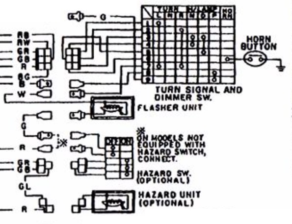
| - | <br><img size=400>http://datsun1200.com/uploads/photos/24405.jpg</img> [http://datsun1200.com/modules/myalbum/photo.php?lid=24405 album] | + | <br>{{Album|24405}}{{Caption|Fig. BE-28 Circuit diagram for turn signal and dimmer switch system}} |
| + | The Hazard switch is normally off and so routes power through G wire to T/S Flasher Unit. This means the T/S Flasher is normally HOT (12V) -- but only if the key is ON. From the T/S Flasher unit the power goes to the T/S Switch on the column. In the center position of course the power stops here. But move the switch to right or left, and the power is fed to the Left or Right circuits to power the exterior bulbs and the the dash bulb. The T/S Flasher Unit causes the power to cycle, resulting in flashing. | ||
| - | The Hazard switch is normally off and so routes power through G wire to T/S Flasher Unit. This means the T/S Flasher is normally HOT (12V) -- but only if the key is ON. From the T/S Flasher unit the power goes to the T/S Switch on the column. In the center position of course the power stops here. But move the switch to right or left, and the power is fed to the Left or Right circuits to power the exterior bulbs and the the dash bulb. The T/S Flasher Unit causes the power to cycle, resulting in flashing. | + | {{Album|28842}}{{Caption|Fig. BE-29 Circuit diagram for hazard lamp system}} |
| + | The BG wire is for the Horn ring contact arm | ||
| + | <br>{{UploadPost|174_58432f233433f.jpg|482620}} | ||
| + | |||
| + | 6-PIN CONNECTOR | ||
| + | R or RY H/L power from Lighting Switch | ||
| + | RG H/L Low | ||
| + | RW H/L High | ||
| + | BG horn button | ||
| + | GR T/S left | ||
| + | GB T/S right | ||
| + | |||
| + | INDIVIDUAL WIRE | ||
| + | W from flasher unit (male spade) | ||
| + | |||
| + | SWITCH with [[Passing Lamp]] button has additional two wires | ||
| + | G (male spade) to passing lamp RELAY | ||
| + | B (female spade) Ground/Earth | ||
| + | |||
| USA: NILES Hazard flasher bolts to right side of column brace (G/L, G/W) | USA: NILES Hazard flasher bolts to right side of column brace (G/L, G/W) | ||
| - | <br>[http://datsun1200.com/modules/myalbum/photo.php?lid=15957 http://datsun1200.com/modules/myalbum/photos/15957.jpg] | + | <br>{{Album|15957}} |
| USA: NILES Turn Signal flasher bolts to left side of column brace | USA: NILES Turn Signal flasher bolts to left side of column brace | ||
| - | <br>[http://datsun1200.com/modules/myalbum/photo.php?lid=15958 http://datsun1200.com/modules/myalbum/photos/15958.jpg] | + | <br>{{Album|15958}} |
| <br>W wire goes into steering column harness, up to the T/S switch | <br>W wire goes into steering column harness, up to the T/S switch | ||
| <br>G is the other wire | <br>G is the other wire | ||
| + | |||
| + | == B210 == | ||
| + | The B210 [[Turn_signal_switch#B210|switch]] uses a 2nd connector, but otherwise the wiring seems similar to the 1200. | ||
| + | |||
| + | 4-pin connector (3 pins populated) | ||
| + | GR LH indicator lamps | ||
| + | GL Flasher unit | ||
| + | GB RH indicator lamps | ||
| + | |||
| + | 6-pin connector (4 or 6 pins populated) | ||
| + | GY Horn relay | ||
| + | 1 R Fuse box | ||
| + | 2 RW? lighting switch | ||
| + | 3 RB? low beams? | ||
| + | 4 RW? high beams? | ||
| + | 5 RY? | ||
| == Dimmer Switch== | == Dimmer Switch== | ||
| Line 83: | Line 134: | ||
| = Lamps = | = Lamps = | ||
| - | == Front Side Marker lamp connector == | + | == Side Marker lamp connector == |
| North America<table class="wiki_table"> | North America<table class="wiki_table"> | ||
| - | <tr><td>B</td><td>Ground</td><td>body connection via screws</td></tr> | + | <tr><td>Bulb</td><td>Ground</td><td></td></tr> |
| - | <tr><td>GL</td><td>(R & L same)</td><td>non-flashing bulb</td></tr> | + | <tr><td>GL (front lamp)</td><td>B</td><td>non-flashing bulb</td></tr> |
| - | </table><br> | + | <tr><td>RL (rear lamp)</td><td>B</td><td>non-flashing bulb</td></tr> |
| + | </table>*NOTE: ground wire is also connected to housing<br><br> | ||
| Other than North America<table class="wiki_table"> | Other than North America<table class="wiki_table"> | ||
| - | <tr><td>B</td><td>Earth/Ground</td><td>body connection via screws</td></tr> | + | <tr><td>--</td><td>Earth/Ground</td><td>body connection via screws</td></tr> |
| <tr><td>GB</td><td>(R.H. side only)</td><td>right indicator bulb</td></tr> | <tr><td>GB</td><td>(R.H. side only)</td><td>right indicator bulb</td></tr> | ||
| <tr><td>GR</td><td>(L.H. side only)</td><td>left indicator bulb</td></tr> | <tr><td>GR</td><td>(L.H. side only)</td><td>left indicator bulb</td></tr> | ||
| Line 103: | Line 155: | ||
| </table> | </table> | ||
| - | ==License plate lamp(s) == | + | == Rear Combo Lamp == |
| - | is simply connected to the rear-harness "tail" circuit (rear running lights -- GW wire). See above. But it is grounded locally, not through a harness wire. | + | Rear combination Lamp Box<table class="wiki_table"> |
| + | <tr><td>REV</td><td>RB</td><td>Reverse lamp circuit</td></tr> | ||
| + | <tr><td>T/S</td><td>WR</td><td>To Left- or Right-side T/S circuit<br>GB (R.H.)<br>GR (L.H.)</td></tr> | ||
| + | <tr><td>STOP</td><td>GY</td><td>Brake light circuit</td></tr> | ||
| + | <tr><td>TAIL</td><td>GW</td><td>Running lights circuit</td></tr> | ||
| + | <tr><td>EARTH</td><td>B</td><td>Rear Comb. lamp "fix bolt"</td></tr> | ||
| + | </table>* The rear wiring harness has a ground wire that bolts to the FIX BOLT, the right-side rear bumper hold-down bolt (inside the car). | ||
| - | == Interior Dome Light== | + | == License plate lamp(s) == |
| - | {{SeeMainArticle!|Room Lamp#Wiring}} | + | The rear [[License Lamp]] is simply connected to the rear-harness "tail" circuit (rear running lights -- GW wire). But it is grounded locally, not through a harness wire. |
| + | |||
| + | <table class="wiki_table"> | ||
| + | <tr><td>TAIL</td><td>GL</td><td>Running lights circuit</td></tr> | ||
| + | <tr><td>LICENSE</td><td>GW</td><td>connects to Running lights circuit</td></tr> | ||
| + | </table>* The license lamp grounds through its bolts, and into the body. For sedan, this is through the [[bumper]]. | ||
| + | |||
| + | {{Album|27142}} | ||
| + | |||
| + | == Interior Dome Light == | ||
| + | {{Main|Room Lamp#Wiring}} | ||
| = Brake lights = | = Brake lights = | ||
| Brake lights (STOP lamps) -- thankfully -- are simply connected on the B110. At the rear light boxes, the GY wires connect to the main harness GY circuit. This is connected to the "Stop Lamp Switch" at the brake pedal. The other side of this switch (both are YG wires) is connected to Fuse Box GY wire ("H" terminal 15A always-hot). So brake lights work when key is off. | Brake lights (STOP lamps) -- thankfully -- are simply connected on the B110. At the rear light boxes, the GY wires connect to the main harness GY circuit. This is connected to the "Stop Lamp Switch" at the brake pedal. The other side of this switch (both are YG wires) is connected to Fuse Box GY wire ("H" terminal 15A always-hot). So brake lights work when key is off. | ||
| - | + | == Instrument panel Brake lamp == | |
| - | ==Instrument panel Brake lamp== | + | |
| The IP brake lamp is not related to the rear brake lamps. Instead it signals if the hand brake is on ("Parking Brake Switch"), or if the master cylinder brake light switch ("Brake System Switch") senses a pressure differential problem. | The IP brake lamp is not related to the rear brake lamps. Instead it signals if the hand brake is on ("Parking Brake Switch"), or if the master cylinder brake light switch ("Brake System Switch") senses a pressure differential problem. | ||
| - | |||
| - | |||
| - | Rear combination Lamp Box | ||
| - | <table border=1 borderwidth=1 bordercolor=black cellspacing=0 cellpadding=2> | ||
| - | <tr><td>REV</td><td>RB</td><td>Reverse lamp circuit</td></tr> | ||
| - | <tr><td>T/S</td><td>WR</td><td>To Left- or Right-side T/S circuit<br>GB (R.H.)<br>GR (L.H.)</td></tr> | ||
| - | <tr><td>STOP</td><td>GY</td><td>Brake light circuit</td></tr> | ||
| - | <tr><td>TAIL</td><td>GW</td><td>Running lights circuit</td></tr> | ||
| - | <tr><td>EARTH</td><td>B</td><td>Rear Comb. lamp "fix bolt"</td></tr> | ||
| - | </table> | ||
| - | The rear wiring harness has a ground wire that bolts to the FIX BOLT, the right-side rear bumper hold-down bolt (inside the car). | ||
| = Reverse Lights = | = Reverse Lights = | ||
| The reverse lamps are simply connected. The Red wire connects to the reverse switch on the side of the transmission. This switch in turn is fed from the G wire at the fuse box ("M" terminal of fuse box -- 10A fuse). It's always in effect, regardless of the Light Switch position. In other words, the Reverse light should work even if the headlights or running lights are off. | The reverse lamps are simply connected. The Red wire connects to the reverse switch on the side of the transmission. This switch in turn is fed from the G wire at the fuse box ("M" terminal of fuse box -- 10A fuse). It's always in effect, regardless of the Light Switch position. In other words, the Reverse light should work even if the headlights or running lights are off. | ||
| - | = Wire color codes = | + | [[Category:Body Electrical System]]{{End}} |
| - | <table border=1 borderwidth=1 bordercolor=black cellspacing=0 cellpadding=2><tr><td>B</td><td>Black</td></tr><tr><td>W</td><td>White</td></tr><tr><td>R</td><td>Red</td></tr><tr><td>Y</td><td>Yellow</td></tr><tr><td>G</td><td>Green</td></tr><tr><td>L</td><td>Blue</td></tr></table> | + | |
| - | + | ||
| - | Wires with two codes: The first letter is the wire color, the second is the stripe color. Example:<blockquote>BW - Black wire with White stripe</blockquote> | + | |
| - | + | ||
| - | [[Category:Body Electrical System]] | + | |
Current revision
The lighting circuits generally use Green wires. Newer 1200 utes differ. The following information is for USA-spec models. Other countries vary slight, see the appropriate Wiring Diagram or click Edit and add the information here.
Contents |
Wire color codes
| B | Black |
| W | White |
| R | Red |
| Y | Yellow |
| G | Green |
| L | Blue |
Wires with two codes: The first letter is the wire color, the second is the stripe color. Example:
BW - Black wire with White stripe
Overview
The lighting circuits generally use Green wires:
- G - IG-hot from Fuse Box
- GY - Brake lights (stop lamps)
- GL or GW - running lights (parking lights)
- GB - R.H. Turn Signal + running lights
- GR - L.H. Turn Signal + running lights
Lighting Switch and Turn signal switch circuits
Dash Lamps
Indicator lamps
* High beam indicator lamp (M.B.) - see Instrument Panel Wiring
* Turn Signal indicator lamps - see below
Warning lamps - see Instrument Panel Wiring
* Brake failure lamp (Japan GL & USA)
* CHG/IGN failure lamp
* Oil pressure indicator lamp
Hazards Wiring
The 4-way Hazards lights are part of the Turn Signal circuit. See #next section.
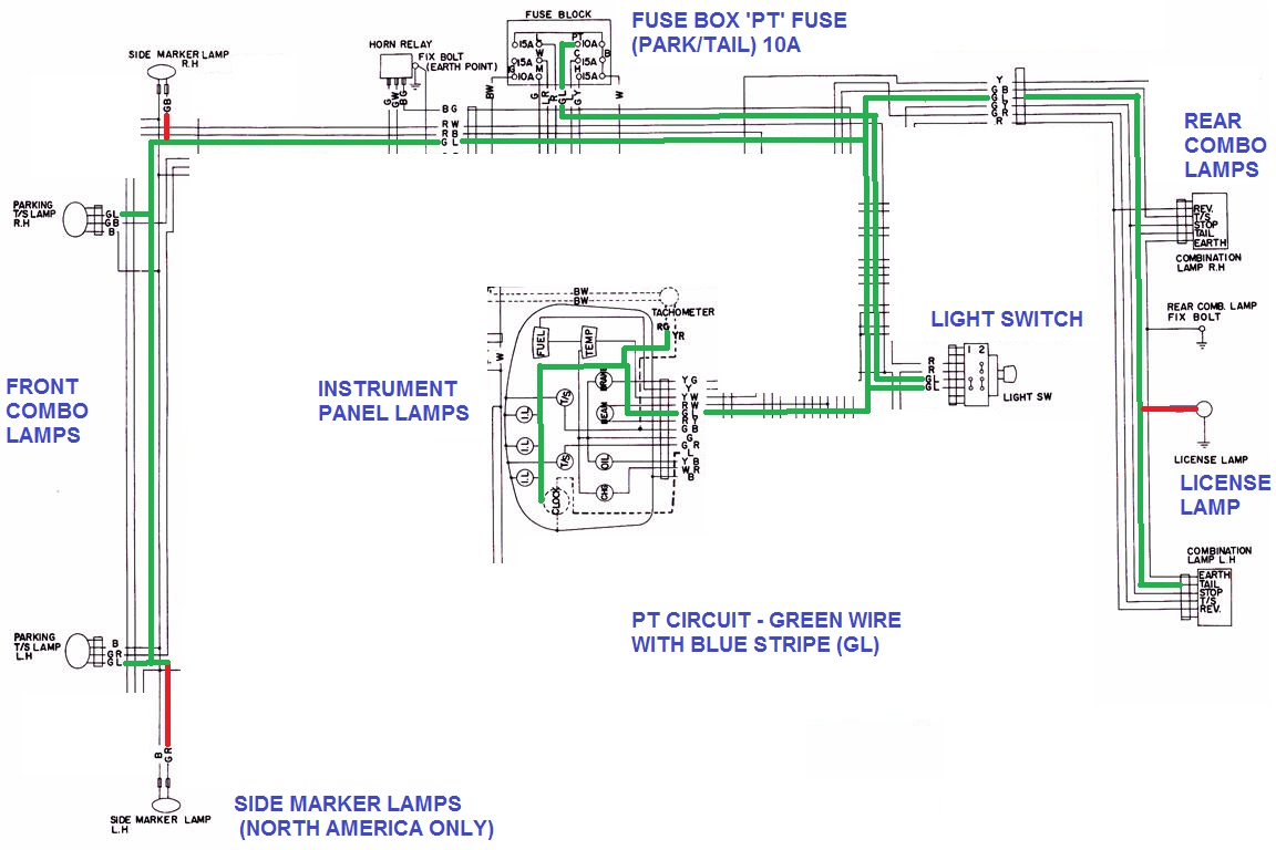
Park/Tail Circuit
When the Lighting Switch is pulled out one or two stops, these light up:
- #Front Combo Lamp "Park" bulbs
- #Rear Combo Lamp "tail" bulbs
- #License Plate Lamp(s)
- #Dash illumination lamps
- #side marker lamps (North America only)
Power comes from the PT fuse in the Fuse Box, and is supplied to the main Green/Blue wire via the Lighting Switch.
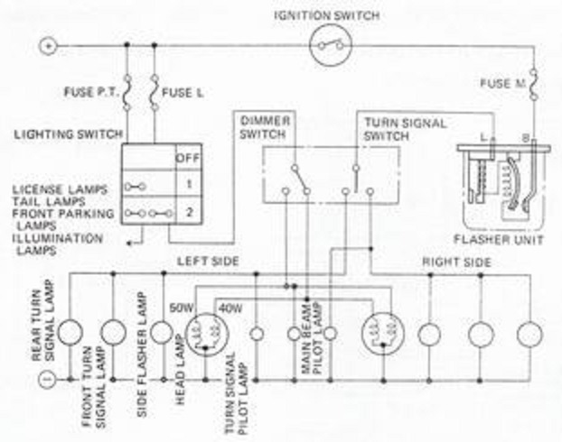
Turn Signals
Also see:
* Turn Signals (include Hazards)
* Flasher unit
* Turn signal switch
The T/S path is as follows:
* 12 volts is provided From the IG side of the Fuse Box
* through the 10A "M" (Meter) terminal via the G (green) wire
* through the Four-Way Flasher Switch (Hazards Switch). NOTE: non-USA export has no Hazard system
* to the Flasher unit
* through the T/S lever on the steering column
* to the lamp bulbs. There is no relay involved
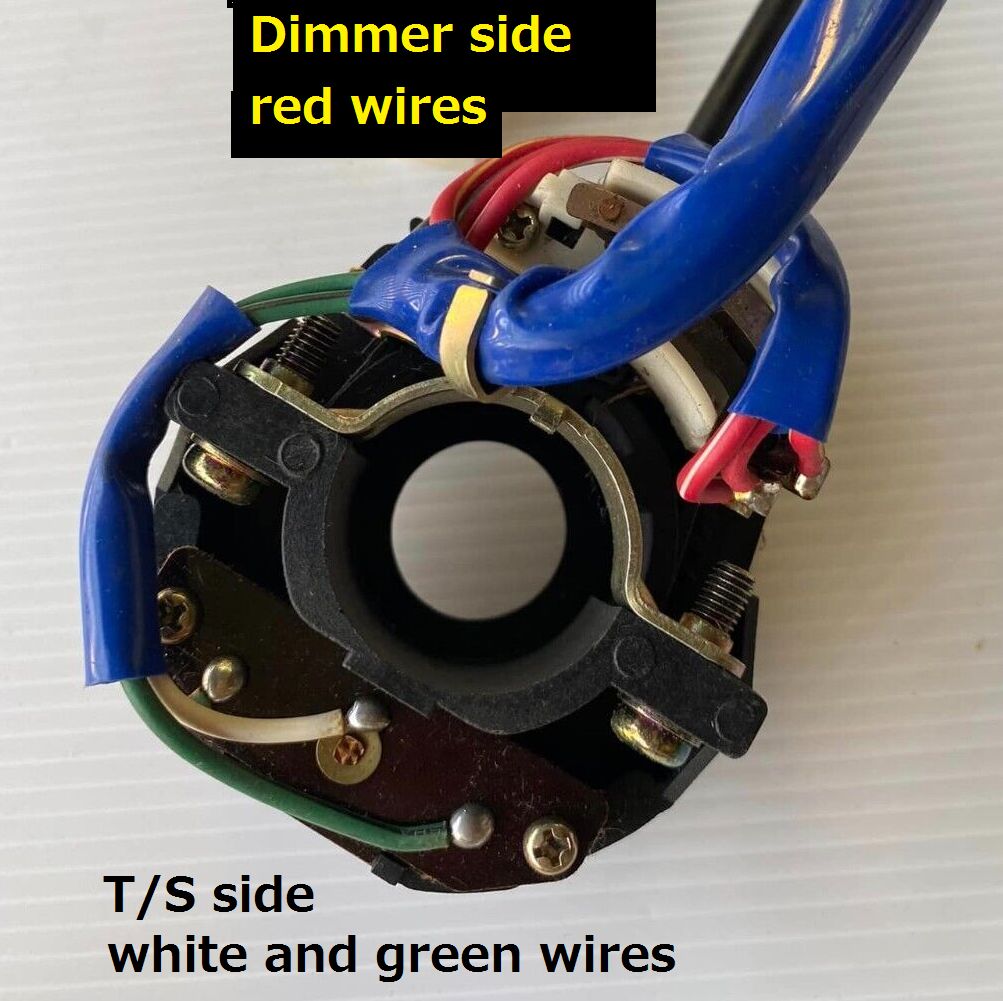
Near the stalk are the three red Dimmer wires for the Head Lights system. Opposite are the T/S wires (two green plus one white). The last wire (not shown) is the blue wire for the Horn button contact.
Dash Indicator Lamps
The Cluster Gauge contains the Left and Right indicator lamps
Japan
Japan-market has Hazard switch but only one Flasher Unit
Late Japan with single-position Hazard switch
USA
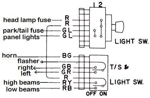
USA circuit - has Hazard switch with seperate Hazard Flasher Unit

The Hazard switch is normally off and so routes power through G wire to T/S Flasher Unit. This means the T/S Flasher is normally HOT (12V) -- but only if the key is ON. From the T/S Flasher unit the power goes to the T/S Switch on the column. In the center position of course the power stops here. But move the switch to right or left, and the power is fed to the Left or Right circuits to power the exterior bulbs and the the dash bulb. The T/S Flasher Unit causes the power to cycle, resulting in flashing.
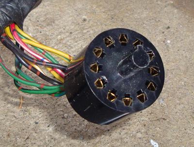
The BG wire is for the Horn ring contact arm

6-PIN CONNECTOR
R or RY H/L power from Lighting Switch
RG H/L Low
RW H/L High
BG horn button
GR T/S left
GB T/S right
INDIVIDUAL WIRE
W from flasher unit (male spade)
SWITCH with Passing Lamp button has additional two wires
G (male spade) to passing lamp RELAY
B (female spade) Ground/Earth
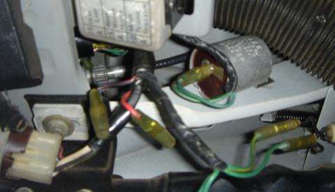
USA: NILES Hazard flasher bolts to right side of column brace (G/L, G/W)
USA: NILES Turn Signal flasher bolts to left side of column brace
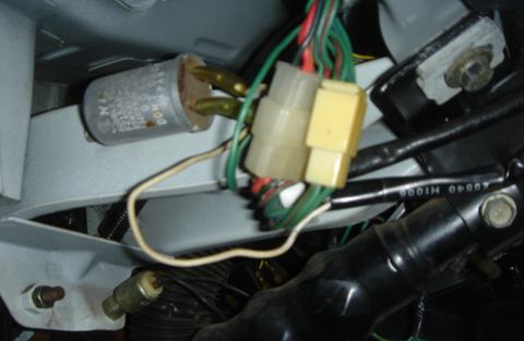
W wire goes into steering column harness, up to the T/S switch
G is the other wire
B210
The B210 switch uses a 2nd connector, but otherwise the wiring seems similar to the 1200.
4-pin connector (3 pins populated)
GR LH indicator lamps
GL Flasher unit
GB RH indicator lamps
6-pin connector (4 or 6 pins populated)
  GY  Horn relay
1 R   Fuse box
2 RW? lighting switch
3 RB? low beams?
4 RW? high beams?
5 RY?
Dimmer Switch
Dimmer Switch (in T/S & Light Switch unit on steering column)
(T/S section of switch listed here)
| ? | T/S hot feed | From Flasher Unit |
| GB | Right-side T/S circuit | To Right-side (GB) T/S circuit To Instrument panel GR wire (right T/S lamp) |
| GR | Left-side T/S circuit | To Left-side (GR) T/S circuit To Instrument panel GR wire (left T/S lamp) |
\*Labeled "Beam" for 1971. The other side of this light is grounded.
Lamps
Side Marker lamp connector
North America| Bulb | Ground | |
| GL (front lamp) | B | non-flashing bulb |
| RL (rear lamp) | B | non-flashing bulb |
Other than North America
| -- | Earth/Ground | body connection via screws |
| GB | (R.H. side only) | right indicator bulb |
| GR | (L.H. side only) | left indicator bulb |
Front Combo Lamp
Front Parking T/S Lamp connector| B | Ground | body connection |
| GB | Right-side T/S circuit (R.H. side only) | From right-side (GB) T/S circuit |
| GR | Left-side T/S circuit (L.H. side only) | From left-side (GR) T/S circuit |
| GL | Dedicated parking lamp circuit | From GL circuit |
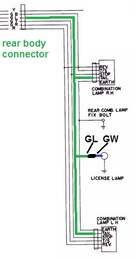
Rear Combo Lamp
Rear combination Lamp Box| REV | RB | Reverse lamp circuit |
| T/S | WR | To Left- or Right-side T/S circuit GB (R.H.) GR (L.H.) |
| STOP | GY | Brake light circuit |
| TAIL | GW | Running lights circuit |
| EARTH | B | Rear Comb. lamp "fix bolt" |
License plate lamp(s)
The rear License Lamp is simply connected to the rear-harness "tail" circuit (rear running lights -- GW wire). But it is grounded locally, not through a harness wire.
| TAIL | GL | Running lights circuit |
| LICENSE | GW | connects to Running lights circuit |
Interior Dome Light
Brake lights
Brake lights (STOP lamps) -- thankfully -- are simply connected on the B110. At the rear light boxes, the GY wires connect to the main harness GY circuit. This is connected to the "Stop Lamp Switch" at the brake pedal. The other side of this switch (both are YG wires) is connected to Fuse Box GY wire ("H" terminal 15A always-hot). So brake lights work when key is off.
Instrument panel Brake lamp
The IP brake lamp is not related to the rear brake lamps. Instead it signals if the hand brake is on ("Parking Brake Switch"), or if the master cylinder brake light switch ("Brake System Switch") senses a pressure differential problem.
Reverse Lights
The reverse lamps are simply connected. The Red wire connects to the reverse switch on the side of the transmission. This switch in turn is fed from the G wire at the fuse box ("M" terminal of fuse box -- 10A fuse). It's always in effect, regardless of the Light Switch position. In other words, the Reverse light should work even if the headlights or running lights are off.