| Revision as of 22:34, 23 April 2018 ddgonzal (Talk | contribs) (->Limiting Mechanical Advance) <- Previous diff |
Revision as of 00:23, 8 May 2019 ddgonzal (Talk | contribs) Next diff -> |
||
| Line 1: | Line 1: | ||
| - | As we all know, more spark advance results in more power, up until the point where the fuel starts pre-detonating (pinging). So the key in create a performance spark curve is '''more advance'''. | + | As we all know, more spark advance results in more power, up until the point where the fuel starts pre-detonating (pinging). So the key in creating a performance spark curve is '''more advance'''. |
| = Overview = | = Overview = | ||
| Line 47: | Line 47: | ||
| #* If it pings at full throttle, set distributor back 2 degrees degree and repeat test | #* If it pings at full throttle, set distributor back 2 degrees degree and repeat test | ||
| #* If it does not ping, advance 2 degrees and repeat test | #* If it does not ping, advance 2 degrees and repeat test | ||
| - | # Reconnect vacuum advance line, and test for pinging at light throttle | + | # Reconnect vacuum advance line, and test for pinging at light throttle. If it pings, retarted the total timing a bit until you have time to finish the curving procedure. Do not drive the car that pings. |
| - | + | INITIAL TIMING: After setting the total timing, turn engine to TDC, then rotate engine until points open (or EI teeth align). Note which timing mark the engine is pointing to. This is your '''new static setting''' to use instead of the factory 5 or 7 degree setting. | |
| - | INITIAL TIMING: After setting the total timing, turn engine to TDC, then rotate engine until points open (or EI teeth align). Note which timing mark the engine is pointing to. This is your new static setting to use instead of the factory 5 or 7 degree setting. | + | |
| = Emission Control = | = Emission Control = | ||
| Line 60: | Line 59: | ||
| Most engines run OK on 5 to 10 degrees initial (base or static) timing. which is not enough to cause starting problems, and will still deliver decent power at the low idling speed. | Most engines run OK on 5 to 10 degrees initial (base or static) timing. which is not enough to cause starting problems, and will still deliver decent power at the low idling speed. | ||
| - | Datsun 1200 distributors are designed for 7 or 5 degrees initial timing. Distributors with 7 have less mechanical advance. With either distributor, the total timing ends up the same. | + | Datsun 1200 distributors are designed for 7 or 5 degrees initial timing. Distributors with 7 have less mechanical advance. With either distributor, the total timing ends up the same. The '5' distributors have a little less pollution at idle. |
| Because this initial figure is factored into the distributor advance curves, do not advance initial timing setting at risk of exceeding the maximum advance at high RPM. | Because this initial figure is factored into the distributor advance curves, do not advance initial timing setting at risk of exceeding the maximum advance at high RPM. | ||
| Line 128: | Line 127: | ||
| (without illustration). | (without illustration). | ||
| - | NOTE: As implemented in many Datsun distributors, "curve" is nominal. The mechanical advance varies practically in a straight line through the RPM range. | + | NOTE: As implemented in many Datsun distributors, "curve" is nominal (is called a "curve" but not really curving). The mechanical advance varies in a straight line through the RPM range. |
| = Advance Characteristics = | = Advance Characteristics = | ||
| Line 176: | Line 175: | ||
| - | Total advance is: | + | Total advance specification is: |
| + | FROM | ||
| 7° initial + 21° (10.5 x 2) mechanical = 28° total | 7° initial + 21° (10.5 x 2) mechanical = 28° total | ||
| - | to | + | TO |
| 7° initial + 25° (12.5 x 2) mechanical = 32° total | 7° initial + 25° (12.5 x 2) mechanical = 32° total | ||
| You want it blueprinted to the latter. | You want it blueprinted to the latter. | ||
| - | |||
| 1970 Centrifugal Advance - part D411-61 | 1970 Centrifugal Advance - part D411-61 | ||
| Line 226: | Line 225: | ||
| 8.5 degree slots | 8.5 degree slots | ||
| <br>{{Album|26837}} | <br>{{Album|26837}} | ||
| + | |||
| Mechanical Advance Governor, showing fly-out weights, springs, and weight pins (which fit into the slots in the advance plate) | Mechanical Advance Governor, showing fly-out weights, springs, and weight pins (which fit into the slots in the advance plate) | ||
| <br>{{Album|24017}} {{Album|26836}} | <br>{{Album|24017}} {{Album|26836}} | ||
Revision as of 00:23, 8 May 2019
As we all know, more spark advance results in more power, up until the point where the fuel starts pre-detonating (pinging). So the key in creating a performance spark curve is more advance.
Contents |
Overview
Spark Timing for performance includes more initial advance, more vacuum advance and earlier centrifugal advance. But ... in no case should the optimum total advance for full-throttle high RPM use be exceeded. This varies by engine type and cylinder head design. Note that if you dial in more initial advance, it will push the total advance, so proceed with caution.
Gasoline engines like lots of advance at part throttle ... but cannot tolerate as much at full throttle. That's why vacuum advance is used, to advance the timing further than normal under part throttle (high vacuum).
For example, if you set the static (base) timing to 20 degrees BTDC at idle, the engine will love it! Unfortunately, at higher RPMs when mechanical advance is added, such a high amount of total advance can damage the engine at full throttle. Instead set it to 10 degrees at 700 RPM and let the vacuum advance pull it to 20+ degrees. Vacuum advance drops to 0 at full throttle so it won't over-advance the engine. This is why the stock systems work as they do.
But you can improve on the stock timing settings. At the very least you can blueprint the distributor spark curves to be on the better side of the factory tolerance.
And even more important for maximum horsepower, you can determine the maximum total advance that works best for your engine (generally around 32 degrees for an A12, or 36 degrees for an L20B). Then you can re-curve the distributor for your engine.
A12 likes 32 degrees total advance
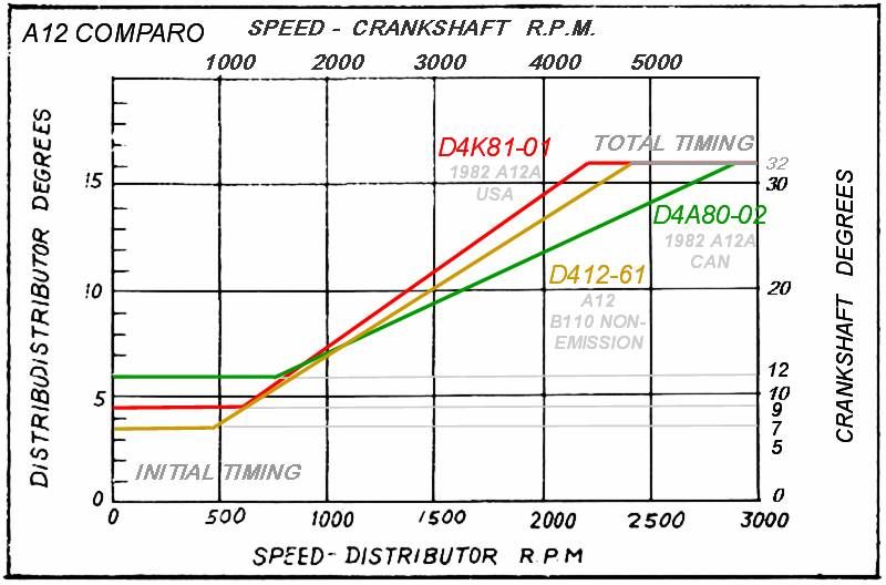
Setting Total Timing
When you install a distributor that has not been measured -- such as a replacement stock distributor, or swapping in one from an A14 or other engine -- after installation you should set the total timing:
 Measured at 4800 RPM
 A12: 32 degrees total
 A14: 34 degrees total
METHOD 1: Degree Marks & Timing Light
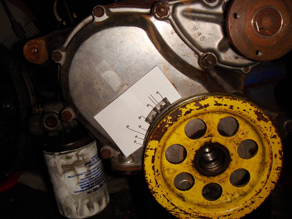
For 1972 and older engines, use this template to mark rim of pulley with paint at 28, 32, and 34 degrees

For 1972-up engines, securely fasten this card to timing cover:
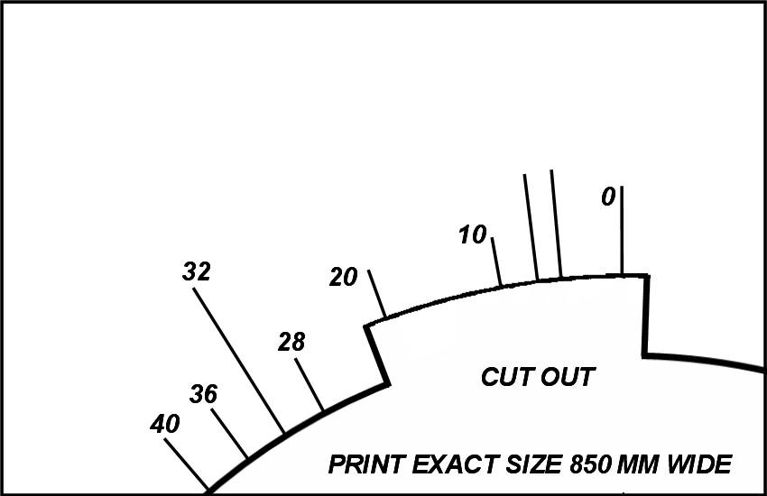
Connect timing light and rev engine until timing stops advancing (should be somewhere before 4800 RPM). Check timing at this maximum advance (note which Pulley mark lines up). If it's not at the total timing desired, turn engine off, rotate distributor appropriate number of degrees, then repeat the full advance check.
Note the timing marks on the A12 plate. These are fine-tuning Advance and Retard marks, very useful for advancing or retarding the timing a degree or two. You can look down past the #1 spark plug, between the engine and the distributor to view the marks.
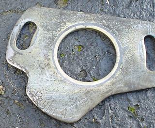
Once set to the desired total advance, finish by verifying engine does not knock/ping by using the Ear Test (Method 2).
METHOD 2: by Ear
- Disconnect and plug vacuum advance line so it will not advance the timing
- Set initial timing to 2 degrees advanced from stock setting (9 or 7 BTDC)
- Road test car at full throttle (up to 4800 RPM). Use a hill to load the engine and second gear to keep road speeds low.
- If it pings at full throttle, set distributor back 2 degrees degree and repeat test
- If it does not ping, advance 2 degrees and repeat test
- Reconnect vacuum advance line, and test for pinging at light throttle. If it pings, retarted the total timing a bit until you have time to finish the curving procedure. Do not drive the car that pings.
INITIAL TIMING: After setting the total timing, turn engine to TDC, then rotate engine until points open (or EI teeth align). Note which timing mark the engine is pointing to. This is your new static setting to use instead of the factory 5 or 7 degree setting.
Emission Control
To reduce certain types of emissions, many Datsun engines introduce transmission gear-selected spark advance cut-out (TCVAS). This is not good for performance, so generally only works in top gear after the car has already accelerated up to speed.
Each year, and in each region, different advance parts (both mechanical and vacuum advance) were fitted to juggle emissions of one type vs another.
Initial Timing
Most engines run OK on 5 to 10 degrees initial (base or static) timing. which is not enough to cause starting problems, and will still deliver decent power at the low idling speed.
Datsun 1200 distributors are designed for 7 or 5 degrees initial timing. Distributors with 7 have less mechanical advance. With either distributor, the total timing ends up the same. The '5' distributors have a little less pollution at idle.
Because this initial figure is factored into the distributor advance curves, do not advance initial timing setting at risk of exceeding the maximum advance at high RPM.
The distributors for emission controlled A12s are designed for 5 degrees base timing. These distributors have more mechanical advance to make up for the lesser base timing, so you get the same Total advance at high RPM.
Total Timing
The total advance timing is the base timing + the mechanical timing. This tops out at 28-32 degrees at between 4200-4800 RPM. 32° is a safe amount of timing for the A12 at full throttle, and won't damage the engine. But if you exceed this it *may* (or may not) cause overheating and/or predetonation which can break the pistons.
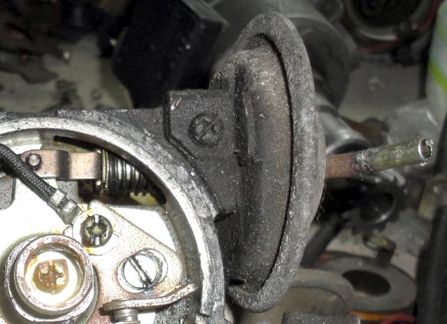
Vacuum advance only works when there is high vacuum, so it does nothing at full throttle. It is not considered in the "total" timing, but adds more timing (and thus more power) at part-throttle conditions.
Determining Optimal
One method you can use to determine the total advance your engine can use you can do at home. Be sure to use a quiet exhaust system so you can hear detonation (or use Detonation Cans, search google for this).
First set it the base timing to stock specification, and plug the vacuum advance line while driving the car.
1. Get the engine to 4400 RPM then floor the throttle and ensure it does not ping. If you use the lower gears (2nd or 3rd), going up a hill will put a good load on the engine. Be careful not to exceed speed limits or put pedestrians at risk.
2. Now advance the timing 2 degrees and repeat the high RPM load test. Listen carefully and do not let it ping for more than it takes to hear it. If it does not ping, repeat Steps 1-2.
3. If it pings, retard timing 1 degree and verify that it no longer pings. Congratulation, you have found the maximum timing for your engine. Make a note of this setting. Better yet, degree the crank pulley and find the total advance figure.
Now it gets complicated. The mechanical (RPM-related) advance curve may be too quick or too slow for your engine.
With the timing at your "optimum max", repeat Step 1 at various lower RPMs. Try 400 RPM increments.
- If you find an RPM at which it pings, the 'curve' is coming on too fast.
- If it doesn't ping at any RPM, the curve may be too slow. You can determing this by advancing the timing 1 degree, and see at which full-load RPM it first starts pinging.
If needed, modify the mechanical advance curve.
Finally, hook up the vacuum advance hose. Now try some part throttle driving. If it pings at any point, the vacuum advance curve is too much. Modify the vacuum can as necessary, or at least back off the timing until it no longer pings.
Note that using high-octane fuel may allow the timing to be advanced 1 or 2 degrees further than regular fuel.
Also differences in the A-type cylinder heads will make a difference. Quench heads (closed chamber) can a take a bit more advance. Open chamber heads may ping sooner and so need to be less advanced.
Total Advance Comparison
Total advance is the initial + centrifugal at full throttle. Because it is full-throttle, the vacuum advance is zero.
A12 typical 32
A14 typical 36
1969 B10/KB10 A10 8° + 13x2 = 34° total
1971 B110 A12 PT 12° +
1970 B110 A12 CAN 7° + 12.5x2 = 32° total
1973 B110 A12 USA 5° + 13.5x2 = 32° total
1974 B210 A13 USA 5° + 13.5x2 = 32° total
1977 B210 A14 USA 10° + 14°x2 = 38° total
* possibly the larger bore can take more advance?
1978 B210 A14 CAN MT (D4A7-02) 10° + 10°x2 = 30°
1978 B210 A14 CAN AT (D4A7-03) 10° + 10°x2 = 30°
1978 B210 A14 USA
1982 CAN A12A 12° + 10°x2 = 32° total D4A80-02
1982 CAN A14 7° + 11.5x2 = 30° total
* emission-control limited
1982 CAN A15 12° + 12x2 = 36° total
1982 USA A12A 9° + 11.5x2 = 32° total D4K81-01
1982 USA A14 7° + 11.5x2 = 30° total
1982 USA A15 7° + 11.5x2 = 30° total
1974 620 L18 USA 34° total
* different combustion characteristics than A-series
NOTE: The distributor curves are listed in each
Datsun Factory Service Manual. Some show a
graph, others have the curve specs in the text
(without illustration).
NOTE: As implemented in many Datsun distributors, "curve" is nominal (is called a "curve" but not really curving). The mechanical advance varies in a straight line through the RPM range.
Advance Characteristics
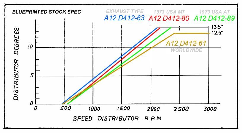
For a factory stock Datsun 1200, including 1.5" exhaust, curves in graphical chart form are presented below.
NOTE: The charts show distributor angle in degrees.
Multiply by two to get degrees at the
crankshaft pulley.
All A-series distributors have similar curves, but vary a little by year and model. Check your Factory Service Manual for your specific model and year to find the curve for your distributor. NOTE: on the side of the distributor is the model number. Mine is D412-63.
Mechanical Advance
Mechanical or centrifugal advance is varied solely by the RPM of the engine. Gasoline engines need a little advance when idling (typically 7 degrees) but a lot at higher RPMs (typically around 35 degrees, but depends on the cylinder head design and size of bore). This is called advance because the spark occurs before the piston approaches the top of the cylinder and the power stroke begins. This is called Before Top Dead Center (BTDC). The advance allows time for the combustion to get going to power the piston down with maximum force.
For the A12, you want a full 32° advance at high RPM. The stock distributors have a mechanical advance tolerance of +- 2 degrees at the crankshaft. That's a huge difference and is the reason why blueprinting your distributor -- even on a stock engine -- is important.
NOTE: If your distributor is on the low side
of the tolerance it can be 4 degrees retarded
and still be in specification!
Stock A12 curves blueprinted to high side of tolerance
Measuring Total Advance
Total advance can be verified with an advance-type Timing Light, or with a standard timing light and additional marks on the crank pulley showing where 32° is.
NOTE: all mechanical advance measurement should
be done with the vacuum advance hose
disconnected and plugged.
- With a standard 138 mm crankshaft pulley, make a new mark exactly 39mm anti-clockwise from the stock TDC mark. You may use crayon or grinder to mark it. This distance is 32 x 1/360 the circumference of the pulley.
- Connect your timing light and start the engine
- Verify the Dwell and Intial timing is correct. See Timing
- Once the initial timing is confirmed, rev the engine to 4800 RPM and verify the new mark is matching with the TDC indicator.
If the full timing is not achieved at high RPM, you can:
- (better) can add more initial timing to get to the 32 mark
- (best) recurve the distributor on a recurving machine
If the full timing is exceeded, retard the base timing enough to compensate.
Standard A12
These are for engines that are not EXHAUST emission-controlled, such as JDM A12s. The engine may have other types of emissions controls such as EVAPO (fuel vapor controls) or CRANK, but those do not affect spark timing.
The factory advance is a nice performance curve for stock engines. But due to factory tolerances could be several degrees too low for best performance and economy. Blueprint your distributor to ensure it is right.
Total advance specification is:
FROM
7° initial + 21° (10.5 x 2) mechanical = 28° total
TO
7° initial + 25° (12.5 x 2) mechanical = 32° total
You want it blueprinted to the latter.
1970 Centrifugal Advance - part D411-61
0° at ~550 rpm
11.5° +-1 degree at 2400 distributor rpm
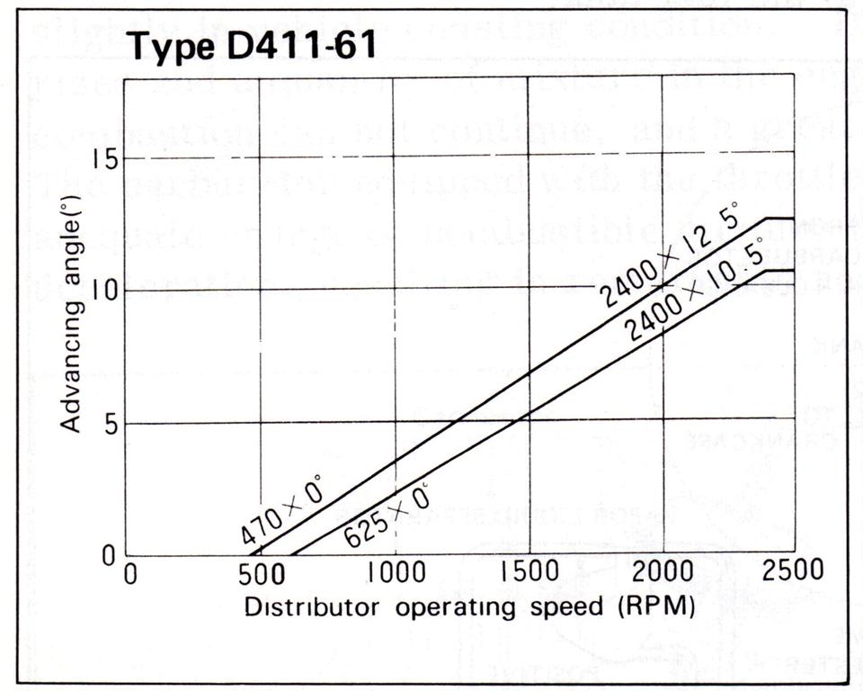
Mechanical advance is all in by 2400 distributor RPM = 4800 crankshaft RPM.
EXHAUST A12
These are for EXHAUST emission-controlled engines, such as USA-specification A12, later JDM 1200s, and possibly later Australia 1200 utes. The spark advance curves are changed to reduce exhaust emissions (unburned HC, carbon monoxide, etc).
EXHAUST controlled A12 engines have lesser initial timing advance (5° compared to 7°) to reduce idle emissions. Because of this these distributors have additional mechanical advance to give you the full total timing.
Total advance is:
5° initial + 27° (13.5 x 2) mechanical = 32° total
tolerance allows down to
5° initial + 23° (11.5 x 2) mechanical = 28° total
1970 Centrifugal Advance - part D412-63
0° at 550 rpm ±100 rpm
12.5° ±1° at 2,100 distributor rpm

Mechanical (Centrifugal) advance is all in by 2100 distributor RPM = 4200 crankshaft RPM.
1973 Centrifugal Advance - part D412-80 for manual transmission
0° at ~600 rpm
12.5° +- 1° at 2,125 +- 25 distributor rpm
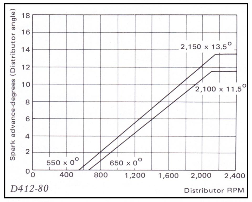
Mechanical (Centrifugal) advance is all in by 2150 distributor RPM = 4300 crankshaft RPM.
1973 Centrifugal Advance - part D412-89 for AUTOMATIC transmission
0° at ~600 rpm
12.5° +- 1° at 2,325 +- 25 distributor rpm
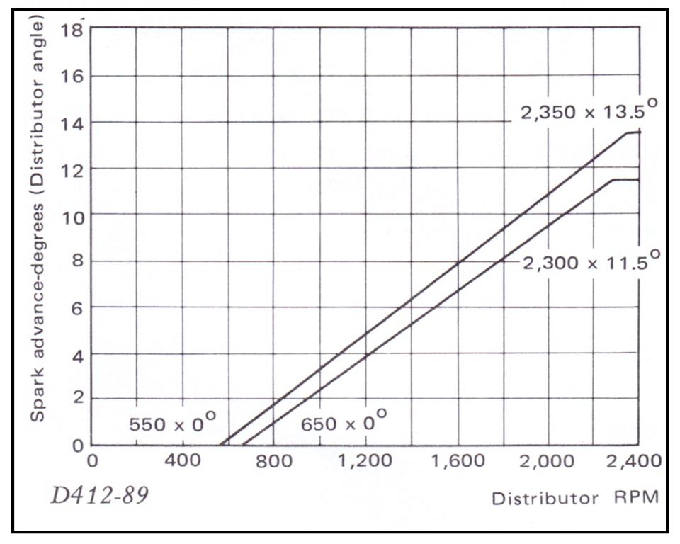
Mechanical (Centrifugal) advance is all in by 2350 distributor RPM = 4700 crankshaft RPM.
Changing Mechanical Advance
The distributor shop can change the mechanical advance by varying the fly-out weights and the springs in the distributor, and by modifying the slots and pins that limit the weight movement.
It appears Datsun varied only the Springs and the Slots (Cam Assembly/Rotor Shaft Assy). All A12A/A14/A15 used the same weight set at least in North America.
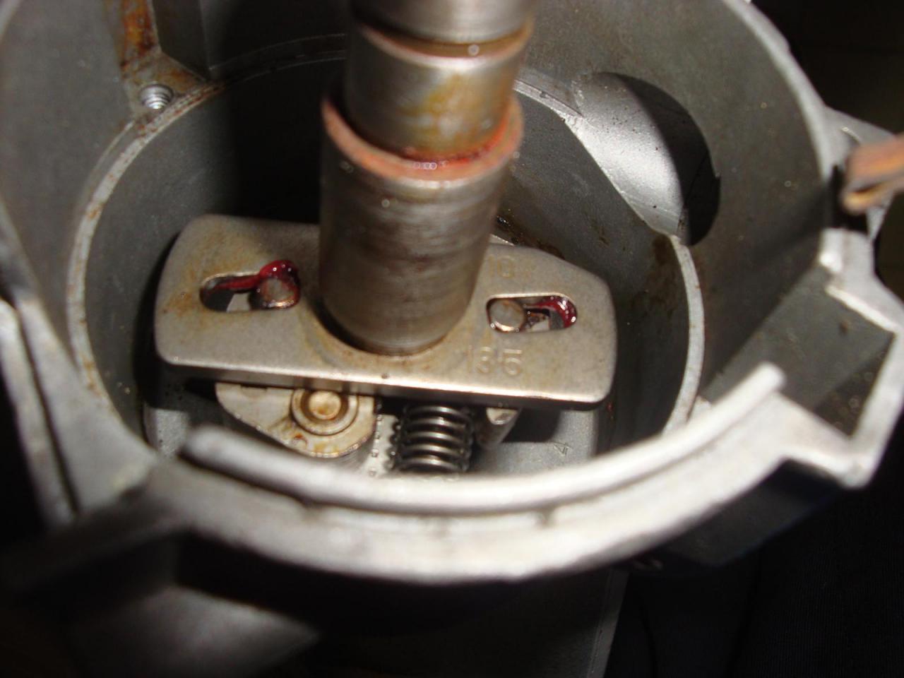
Mechanical Advance Governor, showing fly-out weights, springs, and weight pins (which fit into the slots in the advance plate)
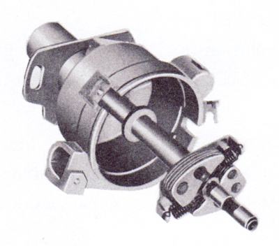

To get access to the governor, follow the disassembly instructions as far as removing the breaker plate.
The distributor expert can balance initial, total, starting RPM and ending RPM against each other. Whereas if you simply rotate the distributor, it only shifts inital and total, but doesn't change the curve.
Datsun 1200 Mitsubishi distributor has top-mount governor
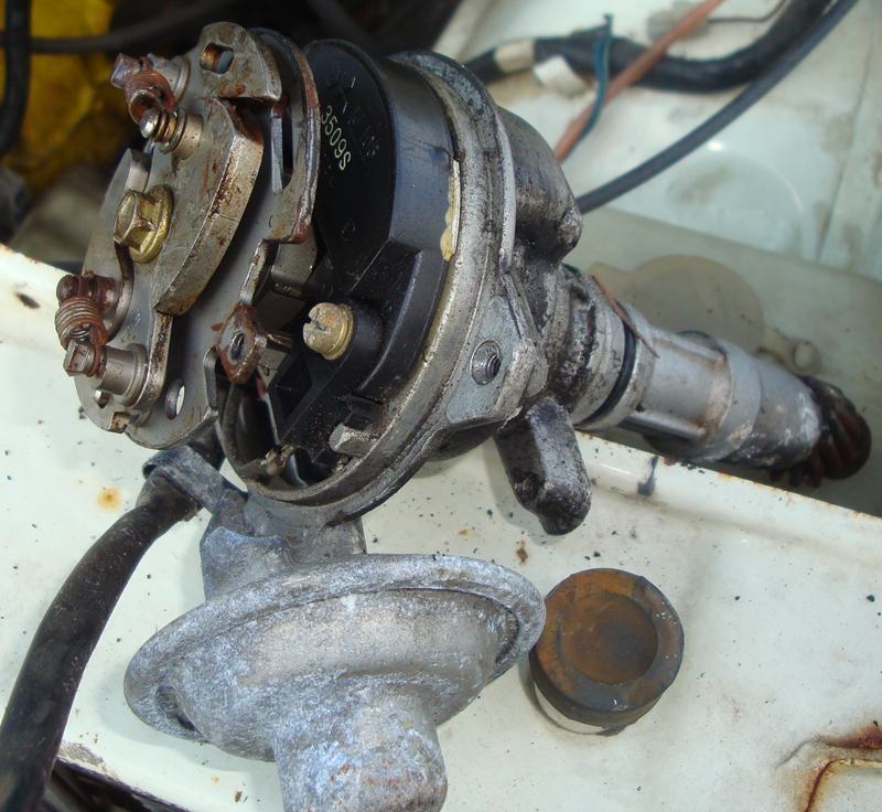
RPM LIMITS
heavier Weights: advance occurs at lower RPM
lighter Weights: advance occurs at higher RPM

heavier Springs: advance occurs at higher RPM
lighter Springs: advance occurs at lower RPM
* Could possible bend the spring anchor tabs
* for adjustment
Changing just one spring or weight
can put a "curve" in the advance, that is,
faster advance in the lower RPMs and slower in
the higher RPMs (or vice-versa).
RANGE of RPM
longer Slots: increase both starting and ending RPMs
shorrer Slots: reduces both starting and ending RPMs
* Slots can be modified on one side to change only
* the beginning or ending RPM
The Hitachi slots and/or pins appear to be assymetrical
smaller diameter Pins: more RPM range
larger diameter Pins: less RPM range
* side of pin facing the slot can be ground down
* or be built-up. Pin width should match slot
* width for the most part, so don't grind the pin
* all around.
Slotted advance plate. Nissan incorporates this part into the Cam Set/Rotor Set.
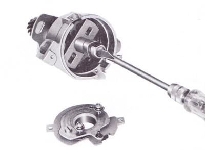
The beginning RPM should be set to a little above idle speed, so that it is inactive at idle. Otherwise you will get a hunting idle as the weights swing a little.
If you change the total amount of advance, you need to reset the base timing to compensate, or vice-versa.
All these considerations are why a distributor shop are recommended.
Governor Parts
Original Datsun 1200 Hitachi Type distributor mechanical advance parts. Type D40 & D41 Hitachi distributors (D4n) were used until about 1975 by most Datsun engine families.
COMMON PARTS
22109-71300 WEIGHT-governor (2) ALL, including JDM L-series
* 173 = PL411-UTK
22108-H2301 ASS'Y-SHAFT A-series Engine [replaced all earlier]
22100-H1001 ASSY-DISTRIBUTOR (HITACHI D411-61) B110 (except GX)
22110-H1000 SET-SPRING, governor
* also used by L14S 1971-1972 510 (Hitachi D411-63)
22132-21005 ASS'Y-cam
** 210 = 510S (1967)
* superceded by 22132-22005
** 220 = P510TK 1600 SSS
22100-H1901 DISTRIBUTOR -1271 (HITACHI D412-63) B110 EXHAUST
22110-H1900 SET-SPRING, governor
22132-H1900 ASS'Y-cam
22108-H1900 SHAFT (0 code with H2300)
22100-H1902 DISTRIBUTOR 1271- (HITACHI D412-63A) AT EXHAUST
22100-H3901 DISTRIBUTOR 1271- (HITACHI D412-80A) MT EXHAUST
22110-H1901 SET-SPRING, governor
22132-H1901 ASS'Y-cam

22100-H7100 DISTRIBUTOR 0772- (HITACHI D412-89) AT EXHAUST
22110-H7100 SET-SPRING, governor
22132-H1901 ASS'Y-cam
22100-H2300 ASSY-DISTRIBUTOR (HITACHI D407-54) (High Gas) GX
* 146 = SP311 Datsun Roadster with R16 (Hitachi 22100-14600)
*  SP311 and 411 SSS both use 22100-14600
22110-14600 SET-SPRING, governor
22132-14605 ASS'Y-cam
22100-18006 ASSY-DISTRIBUTOR (HITACHI D412-53K) (Reg Gas) GX
* also B10 (ex. coupe)
22100-H5700 DISTRIBUTOR-ASSY (HITACHI D412-91) 1973-1975 B210 A12T
22110-18001 SET-SPRING, governor
22132-18005 ASS'Y-cam
22100-25706 ASS'Y-DISTRIBUTOR (D412-57K) B10 Coupe
* 8 BTDC
22110-25700 SET-SPRING, governor
22132-25705 ASS'Y-cam
22100-H5000 DISTRIBUTOR-ASSY (HITACHI D411-89) 1973-1974 B210 A12S
22100-G1600 DISTRIBUTOR-ASSY (HITACHI D411-A3) 1975-1977 B210 A12S.V
22110-H1000 SET-SPRING, governor
22132-18005 ASS'Y-cam
L-series
510
TRI-CURVE
* 0 @ 600 rpm, 6 @ 1175, 9 @ 1465, 12.5 @ 1800
22100-A5502 D412-64 ISO 0870- 510 USA EXHAUST & EVAPO [Dual points]
22108-A5500 SHAFT ASSY SET [L-series type]
22109-A5500 GOVERNOR WEIGHT
22110-A5501 GOVERNOR SPRING SET 0870-0871
240Z 1970-1971
22100-E4601 D612-52 0@500, 12@1415 240Z USA -0871
22108-A3500 ASSY SHAFT
22109-71300 WEIGHT GOVERNOR
22110-E4600 SPRING GOVERNOR
22132-E4600 ASSY CAM
240Z 1972 MT
22100-E4603 240Z USA 0971-0672 MT
22108-A5500 SHAFT SET <> 22108-A5500
22109-A5500 WEIGHT GOVERNOR -0773
22110-E4602 SPRING GOVERNOR -0672
22132-E4600 CAM SET -0672
240Z 1973 MT D611-54 Single-point 7BTDC
* 0@500, 11@1400
22100-N3300 240Z USA 0772-0773 MT
22108-A5500 SHAFT SET <> 22108-A5500
22109-A5500 WEIGHT GOVERNOR -0773
22110-N3300 SPRING GOVERNOR 0772-0773
22132-N3300 CAM SET 0772-0773
240Z 1972-1972 AT
22100-E8000 D614-52 0@700, 9.25@1000, 14@1400 240Z USA 0870-0672 AT
22108-A5500 SHAFT SET <> 22108-A5500
22109-A5500 WEIGHT GOVERNOR -0773
22110-E8005 SPRING GOVERNOR -0672
22132-E8000 CAM SET -0672
240Z 1973 AT D612-54 Dual Point
* 0@500, 12@1480
22100-N3305 240Z USA 0772-0773 AT
22108-A5500 SHAFT SET <> 22108-A5500
22109-A5500 WEIGHT GOVERNOR -0773
22110-N3305 SPRING GOVERNOR 0772-0773
22132-N3305 CAM SET 0772-0773
1972 240Z L24 single & dual carbs
D606-52
* 0@450, 6@1000
* MT:17/650 L24T, 17/550 L24S
* AT:14/700 L24T, 17/560 S24S
1972 240Z L20
D609-56
* 0@550, 9@1200
* MT:10/550, AT:10/650
Parts, D4A Type
Comparison for the D4A/D4F/D4K large-cap hitachi distributors.
22109-A5500 WEIGHT SET, GOVERNOR [all engines]
22110 SPRING SET, GOVERNOR
22132 CAM ASSY/ROTOR SET [incorporates the slots]
22108 SHAFT ASSY [incorporates pins and spring anchors]
1974 A13 22100-H6201 ASSY-DISTRIBUTOR HITACHI D4A02-02
> 5° initial + 27° mechanical = 32 total
22108-H6200 SET-SHAFT
22109-U6001 GOVERNOR-WEIGHT
22110-H6200 SET-SPRING GOVERNOR
22132-H6200 SET-CAM
1975
22100-H7205 ASSY-DISTRIBUTOR (D4A4-03) A14 FED(AUTO) -0775
> ° initial + ° mechanical
22100-H7200 ASSY-DISTRIBUTOR (D4A4-02) A14FED(MANUAL) -0775
> ° initial + ° mechanical
1976
28 @ 4600 POINTS
22100-H7201 ASSY-DISTRIBUTOR (D4A5-04) A14FED(MANUAL) 0875-0776
22100-H7206 ASSY-DISTRIBUTOR (D4A5-05)
* A14 CAN(AUTO) 0875-0776
* A14 FED(AUTO) 0875-0777
> 10° initial + 28° mechanical = 38 total
22132-M5600 SET-CAM
22110-M5601 SET-GOVERNOR SPRING
28 @ 4600 EI
22100-H7302 ASSY-DISTRIBUTOR (D4F5-01) CAL(MANUAL) 0875-0776
> 10° initial + 28° mechanical = 38 total
22132-H7300 ASSY-ROTOR SHAFT
22110-H7301 SET-COVERNOR SPRING
28 @ 4300 EI
2100-H7306 ASSY-DISTRIBUTOR (D4F4-02) CAL(AUTO) -0776
> 8° initial + 28° mechanical = 36 total
22132-H7300 ASSY-ROTOR SHAFT
22110-H7301 SET-COVERNOR SPRING
1977
28 @ 4600 POINTS
22100-H7260 ASSY-DISTRIBUTOR (D4A5-13DS) A14FED(MANUAL) 0876-0777
22100-H7268 ASSY-DISTRIBUTOR (D4A6-05/06?) A14 CAN(AUTO) 0876-0777
22100-H7263 ASSY-DISTRIBUTOR (D4A6-04/05?) A14CAN(MANUAL) 0876-0777
> 10° initial + 28° mechanical = 38 total
22100-H7206 ASSY-DISTRIBUTOR (D4A5-05) A14 FED(AUTO) 0875-0777
* used with different initial timing in 1976
> 8° initial + 28° mechanical = 36 total
22110-M5601 SET-GOVERNOR SPRING
22132-M5600 SET-CAM
28 @ 4600 EI
22100-H7360 ASSY-DISTRIBUTOR (D4F5-03) CAL(MANUAL) 0876-
> 10° initial + 28° mechanical = 38 total
22132-H7300 ASSY-ROTOR
22110-H7301 SET-COVERNOR SPRING
28 @ 4300 EI
22100-H7365 ASSY-DISTRIBUTOR (D4F5-05) CAL(AUTO) 0876-
> 10° initial + 28° mechanical = 38 total
22132-H7300 ASSY-ROTOR
22110-H7301 SET-COVERNOR SPRING
1978
20-degree @ 4800 CAN
22100-H7601 ASSY-DISTRIBUTOR (D4A7-02) A14CAN(MANUAL) 0877-
22100-H7606 ASSY-DISTRIBUTOR (D4A7-03) A14 CAN(AUTO) 0877-
> 10° initial + 20° mechanical = 30 total
22110-H7601 SPRING
22132-H7601 ROTOR SHAFT
28-degree @ 4600 EI
22100-H7265 DISTRIBUTOR ASSY(D4F6-03) FED(AUTO) 0877-
> 8° initial + 28° mechanical = 36 total
22100-H7360 ASSY-DISTRIBUTOR (D4F5-03) CAL+FED.MT 0876-
22100-H7365 ASSY-DISTRIBUTOR (D4F5-05) CAL(AUTO) 0876-
> 10° initial + 28° mechanical = 38 total
22110-H7301 SPRING
22132-H7300 ROTOR SHAFT
28-degree @ 4800 FU
22100-H7680 DISTRIBUTOR-ASSY (D4F7-01) FED(GFU) 0877-
> 5° initial + 28° mechanical = 33 total
22110-H7780 SET-GOVERNOR SPRING
22132-H7780 ROTOR SHAFT-ASSY
B310
D4A80-02 1982 CAN A12A 12° initial + 10° mechanical
Spring set: 22110-H7601
Weight set: 22109-A5500
Cam ass'y: 22132-H7601
NA B310 A14/A15
Spring set
 22110-H9100 FED
 22110-H9160 CAL
 22110-H9300 CAN
Cam ass'y:
 22132-H9100 FED
 22132-H9160 CAL
 22132-H9300 CAN

NA B210
1978 FED AUTO
springs: 22110-H7301
cam/rotor: 22132-H7300
shaft: 22108-H7300
1975 CAL MT
springs: 22110-H7301 or 22110-H7300
cam/rotor: 22132-H7300
shaft: 22108-H7300
1974-1976 FED MT
springs:
 1974 22110-H7200
 1975- 22110-M5601
cam/rotor: 22132-M5600
shaft: 22108-M5600
Limiting Mechanical Advance
Locked distributor advance works great at high-RPM, high-boost condition -- which is where racers spend most of their time, so it works well for racing. For a street engine, you will have a more flexible, more powerful engine at all RPMs by NOT locking the distributor, but by limiting the advance.
In the distributor, weld the advance slots partially to limit mechanical advance. If you end up with too little advance, you can file the slots a bit longer to increase the range
mechanical advance
* stock range: about 25 degrees
* Hi-comp (12:1): perhaps 23 degrees
* High-boost: maybe 18 degrees
Total advance = initial (7 degrees) + Mechanical Advance (25 degrees) = 32 degrees. Lower this slightly for ultra-high compression and lower it a lot for a boosted engine.
This will enable approximately the right advance for varying RPMs, and make the most HP at each RPM.
Making the slots small is what changes the amount of advance.
See these slots? Unbolt the part, then weld the slot to limit how long the slot is. Shorter slots mean very little mechanical advance. You could weld it so the pins barely fit in (no advance), but it is beneficial to have some advance even on a turbo motor.

Pins on the fly-out governor weights fit into the slots

Here's a good picture showing the slots JB-Welded to severely limit mechanical advance:
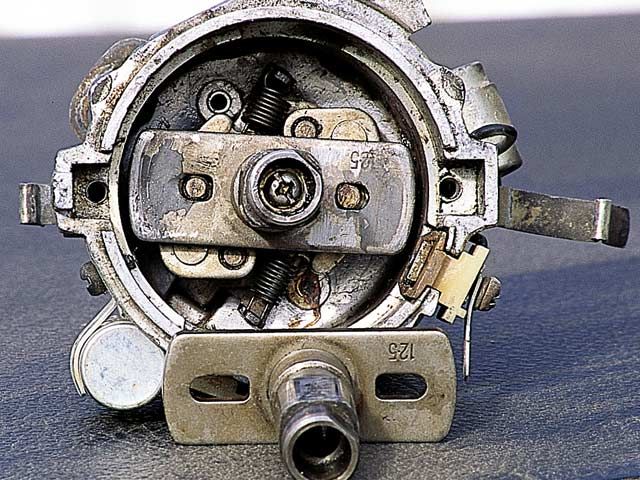
What about the distributor weights? Don't they need to be changed/modified? They have nothing to do with the amount of advance. Instead, they control when (what RPM) the advance occurs at. Along with the springs, the weights control whether all the advance occurs by 3000 RPM or by 4500 RPM or whenever. So while you can modify them, they won't limit the amount of spark advance.
Lock the distributor advance
With a programmable ignition controller, the distributor advance mechanism can be locked, and the box takes over the exact timing curve. Controllers can be an ECU such as MegaSquirt and other advanced ECUs, or a standalone ignition box such as Black Box or MSD.
To lock the distributor timing:
- to disable vacuum advance: do not connect a vacuum line
- to disable mechanical advance: fully weld or fully epoxy the advance slots
Vacuum Advance
1973 Vacuum Advance - part D412-80 for manual transmission
- 0° at 6 inHg (inches of mercury)
- 6.5° at 9.5 inHg
Also See
* Spark Curve Comparison

![[Datsun 1200 encyclopedia]](/wiki/upload/wiki.png)
